�½� 1�����
Chapter
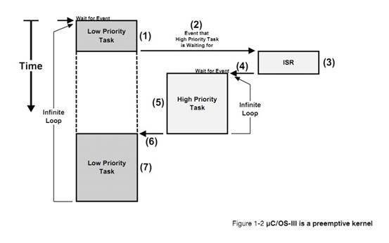
1, Introduction. This chapter.
�½� 2��Ŀ¼���ļ�������½ڽ����� uC/OS-III ������Ŀ¼�ṹ���ļ����˽���Щ�ļ��DZ���ģ���Щ�ļ��ñ��������ģ��Ĺ��ܵȡ�
Chapter
2, Directories and Files. This chapter explains the directory structure and
files needed to build a ��C/OS-III-based application. Learn about the files that
are needed, where they should be placed, which module does what, and more.
�½� 3:��ʼѧϰ uC/OS-III��������½��У�ѧϰ�������úͿ�ʼ���� uC/OS-III ��Ӧ�á�
Chapter
3, Getting Started with ��C/OS-III. In this chapter, learn how to properly
initialize and start a ��C/OS-III-based application.
�½� 4���ٽ�Ρ�������ʲô���ٽ�Σ���ô�����ٽ�Ρ�
Chapter
4, Critical Sections. This chapter explains what critical sections are, and how
they are protected.
�½� 5�����������������ʵʱ�ں�������Ҫ�IJ��֣��ڶ������й�������
Chapter
5, Task Management. This chapter is an introduction to one of the most
important aspects of a real-time kernel, the management of tasks in a
multitasking environment.
�½� 6���������С����� uC/OS-III ��ô��Ч�������еľ�������
Chapter
6, The Ready List. In this chapter, learn how ��C/OS-III efficiently keeps track
of all of the tasks that are waiting to execute on the CPU.
�½� 7�� ������ȡ������� uC/OS-III �ĵ����㷨��
Chapter
7, Scheduling. This chapter explains the scheduling algorithms used by
��C/OS-III, and how it decides which task will run next.
�½� 8���������л���������ʲô���������л����������������ָ��Ĺ��̡�
Chapter
8, Context Switching. This chapter explains what a context switch is, and
describes the process of suspending execution of a task and resuming execution
of a higher-priority task.
�½� 9���жϹ����������� uC/OS-III ��δ��� ISRs ������δԤ�������Լ�Ϊʲô uC/OS-III ֧�ּ������е��жϿ�������
Chapter
9, Interrupt Management. Here is how ��C/OS-III deals with interrupts and an
overview of services that are available from Interrupt Service Routines (ISRs).
Learn how ��C/OS-III supports nearly any interrupt controller.
�½�10�������б����������λ�ȴ�һ���¼�����Դ����ͣ���С������б����������Щ�ȴ��е������½����� uC/OS-III ����ι�����Щ�б��ġ�
Chapter
10, Pend Lists (or Wait Lists). Tasks that are not able to run are most likely
blocked waiting for specific events to occur. Pend Lists (or wait lists), are
used to keep track of tasks that are waiting for a resource or event. This
chapter describes how ��C/OS-III maintains these lists.
�½� 11��ʱ�������uC/OS-III �ķ��������û�������������ʱ�ޡ���������ֹͣ����ֱ�����ָ�������½�Ҳ��������ʱ��ʶ��α��ָ���������ȡ��ǰʱ������ֵ����������ʱ������ֵ��
Chapter
11, Time Management. In this chapter, learn about ��C/OS-III��s services that allow
users to suspend a task until some time expires. With ��C/OS-III, specify to
delay execution of a task for an integral number of clock ticks or until the
clock-tick counter reaches a certain value. The chapter will also show how a
delayed task can be resumed, and describe how to get the current value of the
clock tick counter, or set this counter, if needed.
�½� 12��������ʱ��������uC/OS-III �����û���������������������ʱ������һ����ʱ��ʱʱ���������Ա����á���ʱ�����Ա�����Ϊһ���ԵĻ��������Եġ�����½ڻ������˶�ʱ������ģ��Ĺ������̡�
Chapter
12, Timer Management. ��C/OS-III allows users to define any number of software
timers. When a timer expires, a function can be called to perform some action.
Timers can be configured to be either periodic or one-shot. This chapter also
explains how the timer-management module works.
�½� 13����Դ�����������˶��ֹ�����Դ�ļ��ɡ�ÿ�ּ��ɵ��ŵ��ȱ�㶼�ᱻ�ἰ�����������ź����������ź����Ĺ�����
Chapter
13, Resource Management. In this chapter, learn different techniques so that
tasks share resources. Each of these techniques has advantages and
disadvantages that will be discussed. This chapter also explains the internals
of semaphores, and mutual exclusion semaphore management.
�½� 14��ͬ���������� uC/OS-III �ṩ�˵� 2 ��ͬ�������ź������¼���־�顣�Լ�������ͬ��ģ��ʱ�Ĺ��̡�
Chapter
14, Synchronization. ��C/OS-III provides two types of services for
synchronization: semaphores and event flags and these are explained in this
chapter, as well as what happens when calling specific services provided in
this module.
�½� 15����Ϣͨ����uC/OS-III ��������� ISR ֱ�ӷ�����Ϣ������������Ϣ���й���ģ���һЩ����
Chapter
15, Message Passing. ��C/OS-III allows a task or an ISR to send messages to a
task. This chapter describes some of the services provided by the message queue
management module.
�½� 16����������uC/OS-III ����Ӧ��ͬʱ�������ں˶����ź�������Ϣ���У����������ʹ�ȴ��е�������������һ���¼�������ʱʱѸ�ٱ����ѡ�
Chapter
16, Pending on multiple objects. In this chapter, see how ��C/OS-III allows an
application to pend (or wait) on multiple kernel objects (semaphores or message
queues) at the same time. This feature makes the waiting task ready to run as
soon as any one of the objects is posted (i.e., OR condition), or a timeout
occurs.
�½� 17���ڴ������������ uC/OS-III ���ڴ����ģ����ζ�̬�ط���ͻ����ڴ�顣
Chapter
17, Memory Management. Here is how ��C/OS-III��s fixed-size memory partition
manager can be used to allocate and deallocate dynamic memory.
�½� 18����ֲ
uC/OS-III�������ֲ uC/OS-III ���κμܹ���
CPU���½� 19��ʵʱͳ�ơ�uC/OS-III �ṩ��ʵʱ���л����Ĵ�����Ϣ�������������л�������CPU ʹ���ʣ�ÿ�������ƽ����ջʹ������
Chapter
18, Porting ��C/OS-III. This chapter explains, in generic terms, how to port
��C/OS-III to any CPU architecture.
�½� 19��uC/OS-III �� RAM ʹ�����������ж�ʱ�䣬������������ʱ��ȡ���¼ A��uC/OS-III �� API �ֲ����ĸ����� uC/OS-III ���ṩ��API ����
Chapter
19, Run-Time Statistics. ��C/OS-III provides a wealth of information about the
run-time environment, such as number of context switches, CPU usage (as a
percentage), stack usage on a per-task basis, ��C/OS-III RAM usage, maximum
interrupt disable time, maximum scheduler lock time, and more.
2��Ŀ¼���ļ�
����½ڽ������ uC/OS-III ��ģ���Լ������������ǡ�
��C/OS-III
is fairly easy to use once it is understood exactly which source files are
needed to make up a ��C/OS-III-based application. This chapter will discuss the
modules available for ��C/OS-III and how everything fits together.
ͼ 2-1 ��ʾ���� uC/OS-III �ļܹ��Լ���Ӳ���Ĺ�ϵ������Ӳ����ʱ�����жϿ�������ҲӦ�ð��� UARTs��ADCs����̫���ȡ�
Figure
2-1 shows the ��C/OS-III architecture and its relationship with hardware. Of
course, in addition to the timer and interrupt controller, hardware would most
likely contain such other devices as Universal Asynchronous Receiver
Transmitters (UARTs), Analog to Digital Converters (ADCs), Ethernet
controller(s) and more.
����½ڼٶ������ǻ��� Window ƽ̨�ģ����й��ο��ĵ���Ŀ¼�ṹ��Ȼ������Ϊ uC/OS-III ����Դ������ʽ�ṩ�ģ�������Ҳ���Ա����� Unix��Linux�����������Ŀ���ƽ̨��
This
chapter assumes development on a Windows®-based platform and makes references
to typical Windows-type directory structures (also called Folder). However,
since ��C/OS-III is available in source form, it can also be used on Unix, Linux
or other development platforms.
F2-1��1��Ӧ�ô�������빤�̡���Ʒ����ļ���Ϊ�˷��㣬��Щ���ؽ��� APP.C �� APP.H��Main()����Ӧ����
APP.C ������
The
application code consists of project or product files. For convenience, these
are simply called APP.C and APP.H, however an application can contain any
number of files that do not have to be called APP.*. The application code is
typically where one would find main().
F2-1��2���뵼�峧��ͨ�����ṩ�⺯���Կ�����Щ CPU �� MCU �����衣��Щ��dz����ò��Ҹ�Ч����Ϊ����Щ�ļ�û�й涨�����Լٶ�Ϊ*.C��*.H��
Semiconductor
manufacturers often provide library functions in source form for accessing the
peripherals on their CPU or MCU. These libraries are quite useful and often
save valuable time. Since there is no naming convention for these files, *.C
and *.H are assumed.
F2-1��3���弶֧�ְ�ͨ����������ʼ��Ŀ��塣�����ر�LED���̵�������ȡ����ֵ����ȡ�¶ȴ������ȡ�
The
Board Support Package (BSP) is code that is typically written to interface to
peripherals on a target board. For example such code can turn on and off Light
Emitting Diodes (LEDs), turn on and off relays, or code to read switches,
temperature sensors, and more.
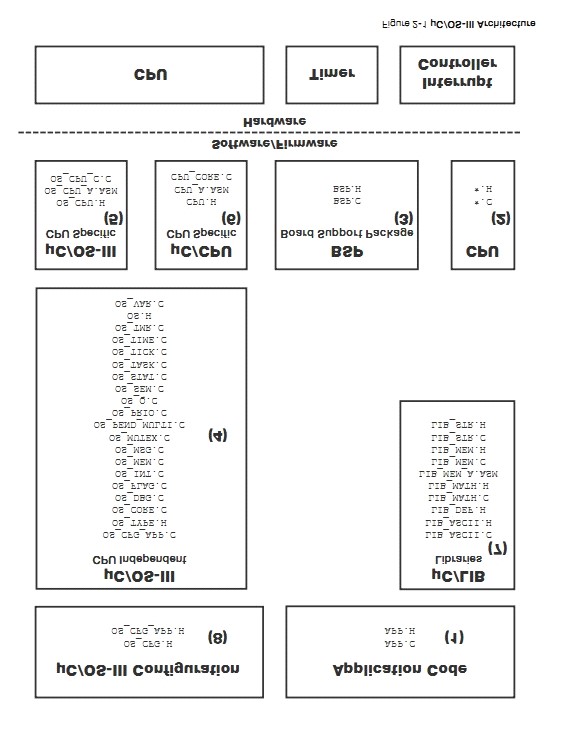
F2-1��4����Щ�� uC/OS-III ���봦�����صĴ��롣��Щ���붼�Ǹ߶���ѭ ANSI C ����
This
is the ��C/OS-III processor-independent code. This code is written in highly
portable ANSI C and is available to ��C/OS-III licensees only.
F2-1��5����Щ uC/OS-III ����������Ӧ��ͬ�ܹ��� CPU������Ϊ port ���ļ����С�uC/OS-III
Դ�� uC/OS-II��uC/OS-II ����ֲ�ɹ��ģ�ֻҪ���иĶ�������ֲ uC/OS-III�������¼ C��
This
is the ��C/OS-III code that is adapted to a specific CPU architecture and is
called a port. ��C/OS-III has its roots in ��C/OS-II and benefits from being able
to use most of the 45 or so ports available for ��C/OS-II. ��C/OS-II ports,
however, will require small changes to work with ��C/OS-III. These changes are
described in Appendix C, ��Migrating from ��C/OS-II to ��C/OS-III�� on page 599.
F2-1��6���� Micrium������ϲ��ȥ�ܽ�
CPU �Ĺ��ܡ���Щ�����жϵ�ʹ�ܺͳ��ܡ�CPU_???���͵��ļ����Ƕ����� CPU �ģ��ڱ���ʱ�õ������ҿ��ܷdz����á�
This
is the ��C/OS-III code that is adapted to a specific CPU architecture and is
called a port. ��C/OS-III has its roots in ��C/OS-II and benefits from being able
to use most of the 45 or so ports available for ��C/OS-II. ��C/OS-II ports,
however, will require small changes to work with ��C/OS-III. These changes are
described in Appendix C, ��Migrating from ��C/OS-II to ��C/OS-III�� on page 599.
F2-1��7��uC/LIB ��һϵ�е�Դ�ļ����ṩ�˳��û����Ĺ������ڴ濽�����ַ�����ASCII ��صĺ�����һЩ���Դ���������ṩ�� stdlib �Ĺ��ܡ���Щ�ļ���Ӧ����Ӧ�ü䣬������������������ֲ��uC/OS-III ����Ҫ��Щ�ļ������� uC/CPU ��Ҫ��
��C/LIB
is of a series of source files that provide common functions such as memory copy,
string, and ASCII-related functions. Some are occasionally used to replace
stdlib functions provided by the compiler. The files are provided to ensure
that they are fully portable from application to application and especially,
from compiler to compiler. ��C/OS-III does not use these files, but ��C/CPU does.
F2-1��8��uC/OS-III ���ܵ������ļ���OS_CFG.H��������Ӧ���У�OS_CFG_APP.H ������ uC/OS-III ����ı������ʹ�С�����ݵĽṹ�����������ջ�Ĵ�С��ʱ�����ʡ��ڴ�ش�С�ȡ�
��C/OS-III
configuration files defines ��C/OS-III features (OS_CFG.H) to include in the
application, and specifies the size of certain variables and data structures
expected by ��C/OS-III (OS_CFG_APP.H), such as idle task stack size, tick rate,
size of the message pool, etc.
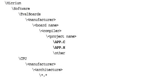
��� Micrium �ṩ�����ӡ���ô���������������µ�Ŀ¼�ṹ��
\Micrium
\Software
\EvalBoards
\<manufacturer>
\<board
name>
\<compiler>
\<project
name>
\*.*
\Micrium
�������Ǵ�������̵ĵط���ͨ��λ�ڵ��Եĸ�Ŀ¼��
This
is where we place all software components and projects provided by Micri��m.
This directory generally starts from the root directory of the computer.
\Software
��Ŀ¼���������ɷ֡�
This
sub-directory contains all software components and projects.
\EvalBoards
��Ŀ¼�а�����������Ĺ��̡�
This
sub-directory contains all projects related to evaluation boards supported by
Micri��m.
\<manufacturer>
�����̵����� �����в�����"<"��">"��
This
is the name of the manufacturer of the evaluation board. The ��<�� and ��>��
are not part of the actual name.
\<board
name>
����������֡�Micrium ͨ������Ϊ uC-Eval-xxxx���� CPU �� MCU�������''xxxx''��
This
is the name of the evaluation board. A board from Micri��m will typically be
called uC-Eval-xxxx where ��xxxx�� represents the CPU or MCU used on the board.
The ��<�� and ��>�� are not part of the actual name.
\<compiler>
����������������
This
is the name of the compiler or compiler manufacturer used to build the code for
the evaluation board. The ��<�� and ��>�� are not part of the actual name.
\<project
name>
�����������磬uC/OS-III ���̻ᱻ����Ϊ"OS-Ex1"��"-Ex1"����������ֵ���� uC/OS-III������Ϊ OS-Probe-Ex1 ��ʾ�����а���uC/OS-III �� uC/Probe��
The
name of the project that will be demonstrated. For example, a simple ��C/OS-III
project might have a project name of ��OS-Ex1��. The ��-Ex1�� represents a project
containing only ��C/OS-III. The project name OS-Probe-Ex1 contains ��C/OS-III and
��C/Probe.
\*.*
��Щ�ǹ��̵�Դ�ļ���main �ļ����Ա�����Ϊ APP*.*��Ŀ¼��Ҳ���������ļ� OS_CFG.H,OS_CFG_APP.H �Լ�������Ҫ��Դ�ļ���
These
are the project source files. Main files can optionally be called APP*.*. This
directory also contains configuration files OS_CFG.H, OS_CFG_APP.H and other
required source files.
�����Ŀ¼�У�����ҵ��뵼�峧���ṩ��������ļ���
The
directory where you will find semiconductor manufacturer peripheral interface
source files is shown below. Any directory structure that suits the
project/product may be used.
\Micrium
The
location of all software components and projects provided by Micri��m.
\Software
The
location of all software components and projects provided by Micri��m.
\CPU
This
sub-directory is always called CPU.
\<manufacturer>
Is
the name of the semiconductor manufacturer providing the peripheral library.
\<architecture>
The
name of the specific library, generally associated with a CPU name or an
architecture.
\*.*
Indicates
library source files. The semiconductor manufacturer names the files.
�弶֧�ְ�ͨ����Ŀ���������������á�ʵʱ�ϣ�д�úõĻ���BSP �������ڶ�����̡�
The
Board Support Package (BSP) is generally found with the evaluation or target
board as it is specific to that board. In fact, when well written, the BSP
should be used for multiple projects.
\Micrium
\Software
\EvalBoards
\<manufacturer>
\<board name>
\<compiler>
\BSP
\*.*
The files
in these directories are available to ��C/OS-III licensees (see Appendix F,
��Licensing Policy�� on page 645).
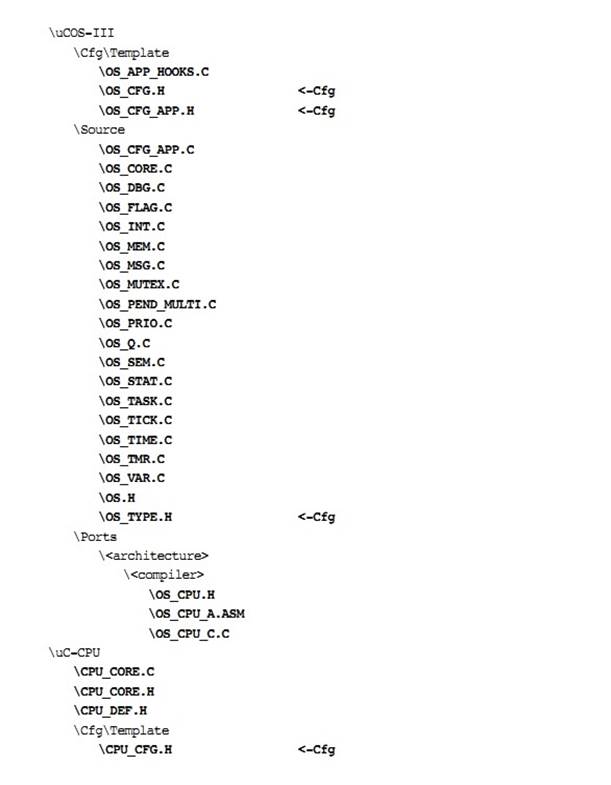
\Micrium
\Software
\uCOS-III
\Cfg\Template
\OS_APP_HOOKS.C \OS_CFG.H
\OS_CFG_APP.H \Source
\OS_CFG_APP.C \OS_CORE.C \OS_DBG.C
\OS_FLAG.C \OS_INT.C \OS_MEM.C \OS_MSG.C \OS_MUTEX.C \OS_PEND_MULTI.C
\OS_PRIO.C \OS_Q.C \OS_SEM.C \OS_STAT.C \OS_TASK.C \OS_TICK.C \OS_TIME.C
\OS_TMR.C \OS_VAR \OS.H
\OS_TYPE.H
\Micrium
Contains
all software components and projects provided by Micri��m.
\Software
This
sub-directory contains all software components and projects.
\uCOS-III
This
is the main ��C/OS-III directory.
\Cfg\Template
This
directory contains examples of configuration files to copy to the project
directory. You will then modify these files to suit the needs of the
application.
OS_APP_HOOKS.C
shows how to write hook functions that are called by ��C/OS-III.
Specifically, this file contains eight empty functions.
OS_CFG.H specifies which
features of ��C/OS-III are available for an application. The file is typically
copied into an application directory and edited based on which features are
required from ��C/OS-III. If ��C/OS-III is provided in linkable object code
format, this file will be provided to indicate features that are available in
the object file. See Appendix B, ����C/OS-III Configuration Manual�� on page 579.
OS_CFG_APP.H is a
configuration file to be copied into an application directory and edited based
on application requirements. This file enables the user to determine the size
of the idle task stack, the tick rate, the number of messages available in the
message pool and more. See Appendix B, ����C/OS-III Configuration Manual�� on page
579.
\Source
The directory
containing the CPU-independent source code for ��C/OS-III. All files in this
directory should be included in the build (assuming you have the source code).
Features that are not required will be compiled out based on the value of #define constants in OS_CFG.H and OS_CFG_APP.H.
OS_CFG_APP.C declares
variables and arrays based on the values in OS_CFG_APP.H.
OS_CORE.C contains core
functionality for ��C/OS-III such as OSInit() to initialize
��C/OS-III, OSSched() for the task
level scheduler, OSIntExit() for the
interrupt level scheduler, pend list (or wait list) management (see Chapter 10,
��Pend Lists (or Wait Lists)�� on page 177), ready list management (see Chapter
6, ��The Ready List�� on page 123), and more.
OS_DBG.C
contains declarations of constant variables used by a kernel aware
debugger or ��C/Probe.
OS_FLAG.C contains the
code for event flag management. See Chapter 14,
��Synchronization��
on page 251 for details about event flags.
OS_INT.C
contains code for the interrupt handler task, which is used when
OS_CFG_ISR_POST_DEFERRED_EN (see OS_CFG.H) is set to 1.
See Chapter 9, ��Interrupt Management�� on page 157 for details regarding the
interrupt handler task.
OS_MEM.C
contains code for the ��C/OS-III fixed-size memory manager, see
Chapter 17, ��Memory Management�� on page 323.
OS_MSG.C contains code
to handle messages. ��C/OS-III provides message queues and task specific message
queues. OS_MSG.C provides
common code for these two services.
See Chapter 15,
��Message Passing�� on page 289.
OS_MUTEX.C
contains code to manage mutual exclusion semaphores, see Chapter 13,
��Resource Management�� on page 209.
OS_PEND_MULTI.C contains the code
to allow code to pend on multiple semaphores or message queues. This is
described in Chapter 16, ��Pending On Multiple Objects�� on page 313.
OS_PRIO.C contains the
code to manage the bitmap table used to keep track of which tasks are ready to
run, see Chapter 6, ��The Ready List�� on page 123. This file can be replaced by
an assembly language equivalent to improve performance if the CPU used provides
bit set, clear and test instructions, and a count leading zeros instruction.
OS_Q.C contains code
to manage message queues. See Chapter 15, ��Message Passing�� on page 289.
OS_SEM.C contains code
to manage semaphores used for resource management and/or synchronization. See
Chapter 13, ��Resource Management�� on page 209 and Chapter 14, ��Synchronization��
on page 251.
OS_STAT.C
contains code for the statistic task, which is used to compute the
global CPU usage and the CPU usage of each of tasks. See Chapter 5, ��Task
Management�� on page 75.
OS_TASK.C contains code
for managing tasks using OSTaskCreate(), OSTaskDel(), OSTaskChangePrio(), and many
more. See Chapter 5, ��Task Management�� on page 75.
OS_TICK.C contains code
to manage tasks that have delayed themselves or that are pending on a kernel
object with a timeout. See Chapter 5, ��Task Management�� on page 75.
OS_TIME.C contains code
to allow a task to delay itself until some time expires. See Chapter 11, ��Time
Management�� on page 183.
OS_TMR.C contains code
to manage software timers. See Chapter 12, ��Timer Management�� on page 193.
OS_VAR.C contains the
��C/OS-III global variables. These variables are for ��C/OS-III to manage and
should not be accessed by application code.
OS.H contains the
main ��C/OS-III header file, which declares constants, macros, ��C/OS-III global
variables (for use by ��C/OS-III only), function prototypes, and more.
OS_TYPE.H contains
declarations of ��C/OS-III data types that can be changed by the port designed
to make better use of the CPU architecture. In this case, the file would
typically be copied to the port directory and then modified. ��C/OS-III in
linkable object library format provides this file to enable the user to know
what each data type maps to. See Appendix B, ����C/OS-III Configuration Manual��
on page 579.
The ��C/OS-III port developer provides these files. See also Chapter
18, ��Porting ��C/OS-III�� on page 335.
\Micrium
\Software
\uCOS-III
\Ports
\<architecture>
\<compiler>
\OS_CPU.H \OS_CPU_A.ASM
\OS_CPU_C.C
\Micrium
Contains all software
components and projects provided by Micri��m.
\Software
This
sub-directory contains all software components and projects.
\uCOS-III
The main
��C/OS-III directory.
\Ports
The location of
port files for the CPU architecture(s) to be used.
\<architecture>
This is the
name of the CPU architecture that ��C/OS-III was ported to. The ��<�� and
��>�� are not part of the actual name.
\<compiler>
The name of the
compiler or compiler manufacturer used to build code for the port. The ��<��
and ��>�� are not part of the actual name.
The files in
this directory contain the ��C/OS-III port, see Chapter 18, ��Porting ��C/OS-III��
on page 335 for details on the contents of these files.
OS_CPU.H contains a
macro declaration for OS_TASK_SW(), as well as
the function prototypes for at least the following functions: OSCtxSw(), OSIntCtxSw() and OSStartHighRdy().
OS_CPU_A.ASM contains the
assembly language functions to implement at least the following functions: OSCtxSw(), OSIntCtxSw() and OSStartHighRdy().
OS_CPU_C.C
contains the C code for the port specific hook functions and code to
initialize the stack frame for a task when the task is created.
��C/CPU consists
of files that encapsulate common CPU-specific functionality and CPU and
compiler-specific data types. See Chapter 18, ��Porting ��C/OS-III�� on page 335.
\Micrium
\Software
\uC-CPU
\CPU_CORE.C \CPU_CORE.H
\CPU_DEF.H
\Cfg\Template
\CPU_CFG.H
\<architecture>
\<compiler>
\CPU.H \CPU_A.ASM \CPU_C.C
\Micrium
Contains all
software components and projects provided by Micri��m.
\Software
This
sub-directory contains all software components and projects.
\uC-CPU
This is the
main ��C/CPU directory.
CPU_CORE.C contains C
code that is common to all CPU architectures. Specifically, this file contains
functions to measure the interrupt disable time of the CPU_CRITICAL_ENTER() and CPU_CRITICAL_EXIT() macros, a
function that emulates a count leading zeros instruction and a few other
functions.
CPU_CORE.H contains
function prototypes for the functions provided in CPU_CORE.C and allocation
of the variables used by the module to measure interrupt disable time.
CPU_DEF.H contains
miscellaneous #define constants used
by the ��C/CPU module.
\Cfg\Template
This directory
contains a configuration template file (CPU_CFG.H) that must be
copied to the application directory to configure the ��C/CPU module based on
application requirements.
CPU_CFG.H determines
whether to enable measurement of the interrupt disable time, whether the CPU
implements a count leading zeros instruction in assembly language, or whether
it will be emulated in C, and more.
\<architecture>
The name of the
CPU architecture that ��C/CPU was ported to. The ��<�� and ��>�� are not part
of the actual name.
\<compiler>
The name of the
compiler or compiler manufacturer used to build code for the ��C/CPU port. The
��<�� and ��>�� are not part of the actual name.
The files in
this directory contain the ��C/CPU port, see Chapter 18, ��Porting ��C/OS-III�� on
page 335 for details on the contents of these files.
CPU.H contains type
definitions to make ��C/OS-III and other modules independent of the CPU and
compiler word sizes. Specifically, one will find the declaration of the CPU_INT16U, CPU_INT32U, CPU_FP32 and many other
data types. This file also specifies whether the CPU is a big or little endian
machine, defines the CPU_STK data type used
by ��C/OS-III, defines the macros OS_CRITICAL_ENTER() and OS_CRITICAL_EXIT(), and contains
function prototypes for functions specific to the CPU architecture, and more.
CPU_A.ASM contains the
assembly language functions to implement code to disable and enable CPU
interrupts, count leading zeros (if the CPU supports that instruction), and
other CPU specific functions that can only be written in assembly language.
This file may also contain code to enable caches, setup MPUs and MMU, and more.
The functions provided in this file are accessible from C.
CPU_C.C contains C
code of functions that are based on a specific CPU architecture but written in
C for portability. As a general rule, if a function can be written in C then it
should be, unless there is significant performance benefits available by
writing it in assembly language.
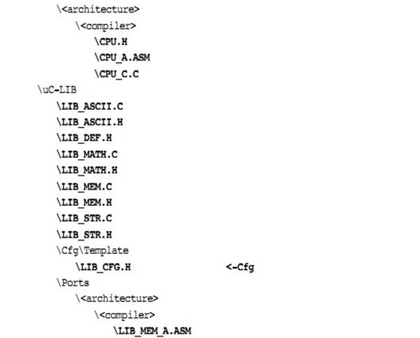
��C/LIB consists of library functions meant to be highly portable and not
tied to any specific compiler. This facilitates third-party certification of
Micri��m products. ��C/OS-III does not use any ��C/LIB functions, however the
��C/CPU assumes the presence of LIB_DEF.H
for such definitions as: DEF_YES,
DEF_NO, DEF_TRUE, DEF_FALSE, DEF_ON, DEF_OFF and more.
\Micrium
\Software
\uC-LIB
\LIB_ASCII.C \LIB_ASCII.H
\LIB_DEF.H \LIB_MATH.C \LIB_MATH.H \LIB_MEM.C \LIB_MEM.H \LIB_STR.C \LIB_STR.H
\Cfg\Template
\LIB_CFG.H \Ports
\<architecture> \<compiler>
\LIB_MEM_A.ASM
\Micrium
Contains all software components and projects provided by Micri��m.
\Software
This sub-directory contains all software components and projects.
\uC-LIB
This is the main ��C/LIB directory.
\Cfg\Template
This directory contains a configuration template file (LIB_CFG.H) that are required to be copied to the application directory to
configure the ��C/LIB module based on application requirements.
LIB_CFG.H determines
whether to enable assembly language optimization (assuming there is an assembly
language file for the processor, i.e., LIB_MEM_A.ASM) and a few other #defines.
����ĸ�Ҫ�ǻ��� uC/OS-III ���̵�����Ŀ¼�ļ�����Ϊ"<-Cfg"
���ļ�ͨ��Ҫ��������Ӧ���ļ����в����ġ�
Below
is a summary of all directories and files involved in a ��C/OS-III-based
project. The ��<-Cfg�� on the far right indicates that these files are
typically copied into the application (i.e., project) directory and edited
based on the project requirements.
3����ʼѧϰ uC/OS-III
uC/OS-III
�Ժ�������ʽ�ṩ�ض��ķ���uC/OS-III �ṩ�ķ����������������ź�������Ϣ���У������ź����ȡ�uC/OS-III �ṩ�˴�Լ 70 �ֹ��ܡ�
��C/OS-III
provides services to application code in the form of a set of functions that
perform specific operations. ��C/OS-III offers services to manage tasks,
semaphores, message queues, mutual exclusion semaphores and more. As far as the
application is concerned, it calls the ��C/OS-III functions as if they were any
other functions. In other words, the application now has access to a library of
approximately 70 new functions.
������½��У����߿������ʹ�� uC/OS-III �Ƕ�ô���ο���¼ A �� uC/OS-III �� API��
In
this chapter, the reader will appreciate how easy it is to start using
��C/OS-III. Refer to Appendix A, ����C/OS-III API Reference Manual�� on page 375,
for the full description of several of the ��C/OS-III services presented in this
chapter.
�ٶ������ѱ�����Ϊǰһ�½�������Ŀ¼���ļ��Ѿ���λ���������� C �������н��С�Ȼ�������½ڶԹ��ߺʹ�����û������Ҫ��
It
is assumed that the project setup (files and directories) is as described in
the previous chapter, and that a C compiler exists for the target processor that
is in use. However, this chapter makes no assumptions about the tools or the
processor that is used.
�б� 3-1
��ʾ����Ӧ���ļ� APP.C �Ķ������롣
Listing
3-1 shows the top portion of a simple application file called APP.C.
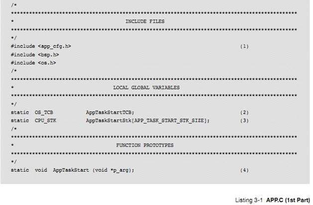
L3-1(1) �������е� C ����һ�������ӱ�Ҫ��ͷ�ļ���Ӧ���С�
As
with any C programs, include the necessary headers to build the application.
APP_CFG.H ���������õ�ͷ�ļ������磬APP_CFG.H �а����� #define ����ȷ�����������ȼ�����ջ��С���Լ��������ԡ�
APP_CFG.H
is a header file that configures the application. For our example, APP_CFG.H
contains #define constants to establish task priorities, stack sizes, and other
application specifics.
BSP.H �� BSP ��ͷ�ļ��������� #define ������ԭ����BSP_Init(),,SP_LED_On()��OS_TS_GET()�ȡ�
BSP.H
is the header file for the Board Support Package (BSP), which defines #defines
and function prototypes, such as BSP_Init(), BSP_LED_On(), OS_TS_GET() and
more.
OS.H �� uC/OS-III ����Ҫͷ�ļ�������������ͷ�ļ���
OS.H
is the main header file for ��C/OS-III, and includes the following header files:
OS_CFG.H
CPU.H
CPU_CFG.H
CPU_CORE.H
OS_TYPE.H
OS_CPU.H
L3-1��2������������ƿ飨OS_TCB����
L3-1(2)
We will be creating an application task and it is necessary to allocate a task
control block (OS_TCB) for this task.
L3-1��3��ÿ��������Ҫ�����Լ��Ķ�ջ����ջ���������ͱ�����CPU_STK����ջ���Ա���̬�ط������ͨ�� malloc()��̬�ط��䡣û�б�Ҫ�ͷŶ�ջ�ռ䣬��Ϊ�����ᱻɾ������ջ��һֱ��ʹ�á�
L3-1(3)
Each task created requires its own stack. A stack must be declared using the
CPU_STK data type. The stack can be allocated statically as shown here, or
dynamically from the heap using malloc(). It should not be necessary to free
the stack space, because the task should never be stopped, and the stack will
always be used.
L3-1��4������һ������ԭ�͡�
This
is the function prototype of the task that we will create.
�ֵ� C Ӧ�ó���ʼ�� main()�����б�
3-2.
Most
C applications start at main() as shown in Listing 3-2.
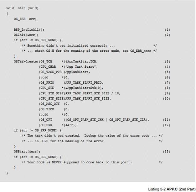
L3-2��1��main()��ʼʱ����һ�� BSP �������ڹر������жϡ��ڴִ������У��ж�������ʱ�ǹرյġ�������Σ�������ʱ�ر����е������ж��Ǹ���ȫ�ġ�
L3-2(1) Start main() by calling a BSP
function that disables all interrupts. On most processors, interrupts are
disabled at startup until explicitly enabled by application code. However, it
is safer to turn off all peripheral interrupts during startup.
L3-2��2������ OSInit(),���ڳ�ʼ��
uC/OS-III��OSInit������ʼ���ڲ����������ݽṹ��ͬʱ���� 2 ���� 5 ���ڲ�������ͳ̶ȣ�
uC/OS-III �봴���������� OS_IdleTask��������û��������������ʱ�����п�������uC/OS-III Ҳ����ʱ������
Call
OSInit(), which is responsible for initializing ��C/OS-III. OSInit() initializes
internal variables and data structures, and also creates two (2) to five (5)
internal tasks. At a minimum, ��C/OS-III creates the idle task (OS_IdleTask()),
which executes when no other task is ready to run. ��C/OS-III also creates the
tick task, which is responsible for keeping track of time.
���������ļ��������õģ�
uC/OS-III �ᴴ��ͳ������
OS_StatTask() ����ʱ������ OS_TmrTask() ���ж϶��д�������
OS_IntQTask()����Щ�����ڵ�����"�������"����ϸ���ܡ�
Depending
on the value of #define constants, ��C/OS-III will create the statistic task
(OS_StatTask()), the timer task (OS_TmrTask()), and the interrupt handler queue
management task (OS_IntQTask()). Those are discussed in Chapter 5, ��Task
Management�� on page 75.
������� uC/OS-III ������ͨ��һ��ָ�� OS_ERR ������ָ�뷵��һ��������š���� OSInit()��ʼ���������гɹ���������ű���Ϊ OS_ERR_NONE������ڳ�ʼ�����ɹ���uC/OS-III �����ִ�еĽ�����ض�Ӧ�Ĵ�����š����� OS.H �еĴ�����š��ر�ģ����еĴ�����Ŷ����� OS_ERR_��Ϊǰ�ġ�
Most
of ��C/OS-III��s functions return an error code via a pointer to an OS_ERR
variable, err in this case. If OSInit() was successful, err will be set to
OS_ERR_NONE. If OSInit() encounters a problem during initialization, it will
return immediately upon detecting the problem and set err accordingly. If this
occurs, look up the error code value in OS.H. Specifically, all error codes
start with OS_ERR_.
OSInit���������� uC/OS-III ����������֮ǰ���á�
It
is important to note that OSInit() must be called before any other ��C/OS-III
function.
L3-2(3) ͨ������ OSTaskCreate������������OSTaskCreate������Ҫ 13 ����������һ�������������ջ�ĵ�ַ��{�������ջ�Ŀ�ʼ��ַ}����� 5 �¡�
L3-2(3) Create a task by calling
OSTaskCreate(). OSTaskCreate() requires 13 arguments. The first argument is the
address of the OS_TCB that is declared for this task. Chapter 5, ��Task
Management�� on page 75 provides additional information about tasks.
L3-2(4)OSTaskCreate����������ÿ������������֡�OS_TCB �д洢��ָ����������ָ�롣������������������ƣ������Կ��ַ���β��
L3-2(4) OSTaskCreate() allows a name to
be assigned to each of the tasks. ��C/OS-III stores a pointer to the task name
inside the OS_TCB of the task. There is no limit on the number of ASCII
characters used for the name.
L3-2(5) �� 3 ��������ָ����������ָ�롣���͵� uC/OS-III ����������ѭ��ִ�е����¡�
L3-2(5) The third argument is the
address of the task code. A typical ��C/OS-III task is implemented as an
infinite loop as shown:
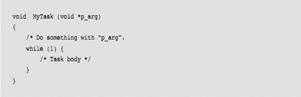
�����һ�ο�ʼʱ����һ��������������������һ�����Ա����õ�
C ������Ȼ�����û����벻������������������������ uC/OS-III ���õġ�
The
task receives an argument when it first starts. As far as the task is
concerned, it looks like any other C function that can be called by the code.
However, the code must not call MyTask(). The call is actually performed
through ��C/OS-III.
L3-2��6��OSTaskCreate()�ĵ��ĸ�������һ��ʵ�Σ���һ�α�����ʱ OSTaskCreate()����������������ݸ������������� MyTask()�е�
"p_arg"��
L3-2(6) The fourth argument of
OSTaskCreate() is the actual argument that the task receives when it first
begins. In other words, the ��p_arg�� of MyTask(). In the example a NULL pointer
is passed, and thus ��p_arg�� for AppTaskStart() will be a NULL pointer.
����IJ��������������ָ�롣���磬�û����Դ������ݽṹ�ȸ�����{���������� void*}
The
argument passed to the task can actually be any pointer. For example, the user
may pass a pointer to a data structure containing parameters for the task.
L3-2��7��OSTaskCreate()�ĵ������������������ȼ������ȼ�ȷ������������Ҫ�Թ�ϵ������ֵԽС���ȼ�Խ�ߡ������������ȼ���ֵΪ 1 �� OS_CFG_PRIO_MAX-2��Ҫ����ʹ�����ȼ�#0 �����ȼ� OS_CFG_PRIO_MAX-1 ����Ϊ��Щ��Ϊ uC/OS-III �����ġ�OS_CFG_PRIO_MAX �DZ���ʱ���õģ��� OS_CFG.H �ж��塣
L3-2(7) The next argument to OSTaskCreate()
is the priority of the task. The priority establishes the relative importance
of this task with respect to the other tasks in the application. A low-priority
number indicates a high priority (or more important task). Set the priority of
the task to any value between 1 and OS_CFG_PRIO_MAX-2, inclusively. Avoid using
priority #0, and priority OS_CFG_PRIO_MAX-1, because these are reserved for
��C/OS-III. OS_CFG_PRIO_MAX is a compile time configuration constant, which is
declared in OS_CFG.H.
L3-2��8���������ջ�Ļ���ַ������ַͨ���Ƿ����������Ķ�ջ������ڴ�λ�á�
L3-2(8) The sixth argument to
OSTaskCreate() is the base address of the stack assigned to this task. The base
address is always the lowest memory location of the stack.
L3-2��9�����߸������ǵ�ַ��ˮӡ��������ջ������ָ��λ��ʱ�Ͳ�������������������½� 5���������У�����ջ�ռ�ֻʣ�� 10%��ʱ�����ƶ�ջ��������
L3-2(9) The next argument specifies
the location of a ��watermark�� in the task��s stack that can be used to determine
the allowable stack growth of the task. See Chapter 5, ��Task Management�� on
page 75 for more details on using this feature. In the code above, the value
represents the amount of stack space (in CPU_STK elements) before the stack is
empty. In other words, in the example, the limit is reached when there is 10%
of the stack left.
L3-2��10��OSTaskCreate()�ĵڰ˸���������������Ķ�ջ��С(�� CPU_STK Ϊ�������Ͷ������ֽ�)�����磬���Ҫ���� 1KB ��С�Ķ�ջ�ռ䣬��Ϊ CPU_STK �� 32 λ�ģ�������������� 256.
L3-2(10) The eighth argument to OSTaskCreate()
specifies the size of the task��s stack in number of CPU_STK elements (not
bytes). For example, if allocating 1 Kbyte of stack space for a task and the
CPU_STK is a 32-bit word, then pass 256.
L3-2��11����������������������������Ϊ��������������ǰ�Ļ����أ�ֱ������Ϊ 0��������һ�������� OSTaskCreate()�Ŀ�ѡ����磬������ʱ��ջ�ᱻ��⣨�ٶ�ͳ��������
OS_CFG.H ��ʹ�ܣ�������ʱ��ջ�ᱻ��ʼ����
L3-2(11) The next three arguments are skipped as
they are not relevant for the current discussion. The next argument to
OSTaskCreate() specifies options. In this example, we specify that the stack
will be checked at run time (assuming the statistic task was enabled in
OS_CFG.H), and that the contents of the stack will be cleared when the task is
created.
L3-2��12��OSTaskCreate()�����һ��������һ��ָ�룬�����ո��ݺ���ִ�н�������صĴ�����š���� OSTaskCreate()����ִ�гɹ���������Ž����� OS_ERR_NONE������᷵�������Ĵ�����ţ��μ� OS.H �д�����ŵĶ��壩��
L3-2(12) The last argument of OSTaskCreate() is a
pointer to a variable that will receive an error code. If OSTaskCreate() is
successful, the error code will be OS_ERR_NONE otherwise, look up the value of
the error code in OS.H (See OS_ERR_xxxx) to determine the problem with the
call.
L3-2��13������ uC/OS-III ������
main()�����е����һ�������ǵ��� OSStart()����ʼ�����������ر�ģ��� OSStart()����֮ǰ uC/OS-III ��ѡ��������ȼ�����������ȼ�������ͨ���� OS_IntQTask()���ٶ��� OS_CFG.H �ж����� OS_CFG_ISR_POST_DEFERRED_EN������������£�OS_IntQTask()����ִ��һЩ�������ij�ʼ��������Ȼ�� uC/OS-III �����л�����һ��������ȼ�������
L3-2(13) The final step in main() is to call
OSStart(), which starts the multitasking process. Specifically, ��C/OS-III will
select the highest-priority task that was created before calling OSStart(). The
highest-priority task is always
OS_IntQTask()
if that task is enabled in OS_CFG.H (through the
OS_CFG_ISR_POST_DEFERRED_EN
constant). If this is the case, OS_IntQTask() will perform some initialization
of its own and then ��C/OS-III will switch to the next most important task that
was created.
OSTaskCreate()�е�һЩָ��û�����塣���ȣ��ڵ��� OSStart() ֮ǰ��������Ҫ����������Ȼ���������Ƽ����ʱ���ֻ����һ��������Ϊ����������� uC/OS-III ����ȷ�� CPU �����ʣ����Բ���
CPU ��ʹ���ʡ����Ӧ����Ҫ������ں˶������ź�������Ϣ���У���ô�Ƽ��ڵ��� OSStart()֮ǰ�������ǡ����ע���жϻ�û�п������⽫��������һ������
AppTaskStart()�����ۡ����б� 3-3
A
few important points are worth noting. For one thing, create as many tasks as
you want before calling OSStart(). However, it is recommended to only create
one task as shown in the example because, having a single application task
allows ��C/OS-III to determine how fast the CPU is, in order to determine the
percentage of CPU usage at run-time. Also, if the application needs other
kernel objects such as semaphores and message queues then it is recommended
that these be created prior to calling OSStart(). Finally, notice that that
interrupts are not enabled. This will be discussed next by examining the
contents of AppTaskStart(), which is shown in Listing 3-3.
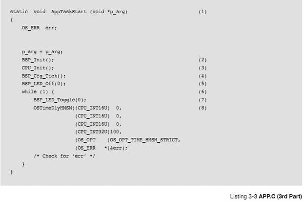
L3-3(1)����ǰ���ᵽ�ģ�һ��������������һ�� C ����������
��p_arg���� OSTaskCreate()���ݸ����� AppTaskStart()�IJ�����
L3-3(1) As previously mentioned, a
task looks like any other C function. The argument ��p_arg�� is passed to
AppTaskStart() by OSTaskCreate(), as discussed in the previous listing
description.
L3-3��2��BSP_Init()���ڳ�ʼ��Ŀ����Ӳ����Ŀ�����ܻ���һЩ GPIO���̵���������������Ҫ�����á������������ BSP.C �ж���ġ�
L3-3(2) BSP_Init() is a Board Support
Package (BSP) function that is responsible for initializing the hardware on an
evaluation or target board. The evaluation board might have General Purpose
Input Output (GPIO) lines that might need to be configured, relays, sensors and
more. This function is found in a file called BSP.C.
L3-3��3��CPU_Init()��ʼ��
uC/CPU �ķ���uC/CPU ���ڲ����ж���Ӧʱ�䣬��ȡʱ������ṩ����ļ�������ָ��ȣ��ٶ��û���ʹ�õĴ�����û�����ֻ��ָ���
L3-3(3) CPU_Init() initializes the
��C/CPU services. ��C/CPU provides services to measure interrupt latency, receive
time stamps, and provides emulation of the count leading zeros instruction if
the processor used does not have that instruction and more.
L3-3��4��BSP_Cfg_Tick()����
uC/OS-III ��ʱ���жϡ�Ϊ�ˣ����������Ҫ��ʼ��һ��Ӳ����ʱ�������ж� CPU ����Ƶ��Ϊ
OS_CFG_TICK_RATE_HZ���� OS_CFG_APP.H �ж��壩��
L3-3(4) BSP_Cfg_Tick() sets up the
��C/OS-III tick interrupt. For this, the function needs to initialize one of the
hardware timers to interrupt the CPU at a rate of:
OSCfg_TickRate_Hz,
which is defined in OS_CFG_APP.H (See OS_CFG_TICK_RATE_HZ).
L3-3��5��BSP_LED_Off()���ڹر�
LED������Ϊ 0 ��ʾ�ر�ȫ���� LED�����Ǹ��û���������ɾ����
L3-3(5) BSP_LED_Off() is a function
that will turn off all LEDs because the function is written so that a zero
argument means all the LEDs.
L3-3��6�����е� uC/OS-III ������Ҫ������Ϊ����ѭ����
L3-3��7��BSP_LED_Toggle()���ڴ� LED��ͬ���ģ�����Ϊ 0 ��ʾ��ȫ�� LED���IJ���Ϊ 1 ��ʾ���Ϊ#1 �� LED �������ĸ� LED ���Ϊ#1
�أ���ȡ��������ߡ��ر�ģ����Խ� LED �IJ�����װΪ��
BSP_LED_On(),BSP_LED_Off()��BSP_LED_Toggle()�ĺ��������Ǹ�ϲ������ LED Ϊ��λ(1,2,3 ��)��ÿһλ��Ӧһ���˿�ֵ���ú������û���������ɾ��
L3-3��8�����ÿ��������Ե��� uC/OS-III �еĺ����������������һ���¼����ź��������������жϵ���Ϣ���������������������Ϣ����������������������õȴ�����(ͨ������ OSTimeDly() ����
OSTimeDlyHMSM())���½� 11��ʱ������������˵ȴ����������Ϣ��
�б� 3-4 �� 3-8 �Ĵ���չʾ��һ����������������������ӣ�һ���� mutex��һ�����ź�����һ������Ϣ���С�
The
code of Listing 3-4 through Listing 3-8 shows a more complete example and
contains three tasks: a mutual exclusion, semaphore, and a message queue.
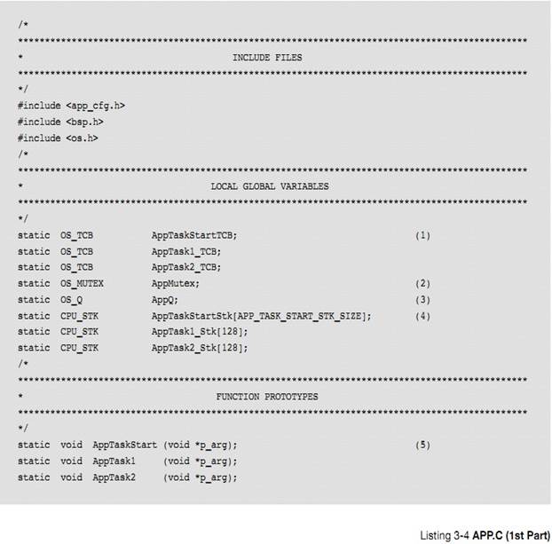
L3-4��1) �ֱ�Ϊÿ���������һ�� OS_TCB��
L3-4(1) Allocate storage for the
OS_TCBs of each task.
L3-4��2�������ź�����mutex����һ���ں˶���(һ���ṹ��)�����ڱ���������Դ������Ҫ���ʹ�����Դ�ͱ����Ȼ�� mutex��mutex ��ӵ����ʹ���������Դ��ͱ����ͷ���� mutex���������ʾ����������̡�
L3-4(2) A mutual exclusion semaphore
(a.k.a. a mutex) is a kernel object (a data structure) that is used to protect
a shared resource from being accessed by more than one task. A task that wants
to access the shared resource must obtain the mutex before it is allowed to
proceed. The owner of the resource relinquishes the mutex when it has finished
accessing the resource. This process is demonstrated in this example.
L3-4��3����Ϣ������һ���ں˶���ISR ���������ֱ�ӷ�����Ϣ����һ�����������ƶ�һ����Ϣ�����䷢�͵�Ŀ���������Ϣ���С�Ŀ������ȴ���Ϣ�ĵ�������Ϣ�����ˣ�Ŀ������ȡ����Щ��Ϣ�������Ϣ����Ϊ�գ�Ŀ�꽫�ᱻ�����ڹ�������в�����Ϣ���б�����ϵ��������̽�������������н��ܡ�
L3-4(3) A message queue is a kernel
object through which Interrupt Service Routines (ISRs) and/or tasks send
messages to other tasks. The sender ��formulates�� a message and sends it to the
message queue. The task(s) wanting to receive these messages wait on the
message queue for messages to arrive. If there are already messages in the
message queue, the receiver immediately retrieves those messages. If there are
no messages waiting in the message queue, then the receiver will be placed in a
wait list associated with the message queue.This process will be demonstrated
in this example.
L3-4 ��4��Ϊÿ����������ջ��{������
CPU_STK ���ͣ�����32 λ�ģ����� 128 �� CPU_STK ��λ 512B}
L3-4(4) Allocate a stack for each
task.
L3-4��5���û���Ҫ������Щ����
L3-4(5) The user must prototype the
tasks.
�б� 3-5 չʾ�� C ���Ե���ڡ���main()������
Listing
3-5 shows the entry point for C, main().
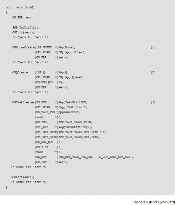
L3-5��1)���� OSMutexCreate()����һ�� mutex��ָ�� OS_MUTEX ����ĵ�ַ������½� 13"��Դ����"��
L3-5(1)
Creating a mutex is simply a matter of calling OSMutexCreate(). Specify the
address of the OS_MUTEX object that will be used for the mutex. Chapter 13,
��Resource Management�� on page 209 provides additional information about mutual
exclusion semaphores.
����Ϊ mutex ����һ�� ASCII ���֣��Ե��Ի�����ô���
You
can assign an ASCII name to the mutex, which is useful when debugging.
L3-5��2)���� OSQCreate()������Ϣ���У���ָ�� OS_Q ����ĵ�ַ��
����½� 15����Ϣ���ݡ���
L3-5(2)
Create the message queue by calling OSQCreate() and specifying the address of the
OS_Q object. Chapter 15, ��Message Passing�� on page 289 provides additional
information about message queues.
Ϊ��Ϣ����������
Assign
an ASCII name to the message queue.
�������Ϣ���пɽ�����Ϣ�ĸ��������ֵ������� 0�������Ϣ�߷�����Ϣ����������Ϣ��������ij�����������ô��Ϣ���ᱻ��ʧ������ͨ��������Ϣ���еĴ�С�����ṩ��Ϣ������������ȼ����������������
Specify
how many messages the message queue is allowed to receive. This value must be
greater than zero. If the sender sends messages faster than they can be
consumed by the receiving task, messages will be lost. This can be corrected by
either increasing the size of the message queue, or increasing the priority of
the receiving task.
L3-5��3����һ��Ӧ����������
L3-5(3) The first application task is
created.
�б� 3-6 չʾ������ڶ�������ȿ�ʼ������
Listing
3-6 shows how to create other tasks once multitasking as started.
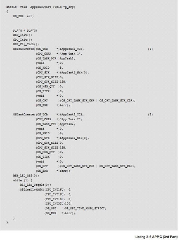
L3-6��1��ͨ������ OSTaskCreate������������#1�������������������ȼ����ڴ���������������ȼ���uC/OS-III ��ת��ִ������#1. �����������������ȼ�С�ڴ���������������ȼ���OSTaskCreate() ���᷵�� AppTaskStart()����ִ������Ĵ��롣
L3-6(1) Create Task #1 by calling
OSTaskCreate(). If this task happens to have a higher priority than the task
that creates it, ��C/OS-III will immediately start Task #1. If the created task
has a lower priority, OSTaskCreate() will return to AppTaskStart() and continue
execution.
L3-6��2������#2 ����������������ȼ�����
AppTaskStart()�����ȼ� ��
��ô uC/OS-III ��������ȥִ������#2��
L3-6(2) Task #2 is created and if it
has a higher priority than AppTaskStart(), ��C/OS-III will immediately switch to
that task.
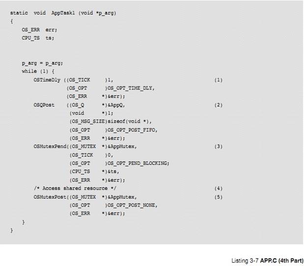
L3-7��1����������ִ��ǰ�ȵȴ�һ��ʱ������� uC/OS-III ��ʱ��Ƶ��Ϊ 1000HZ����ô�������ÿ���뱻ִ��һ�Ρ�
L3-7(1) The task starts by waiting
for one tick to expire before it does anything useful. If the ��C/OS-III tick
rate is configured for 1000 Hz, the task will execute every millisecond.
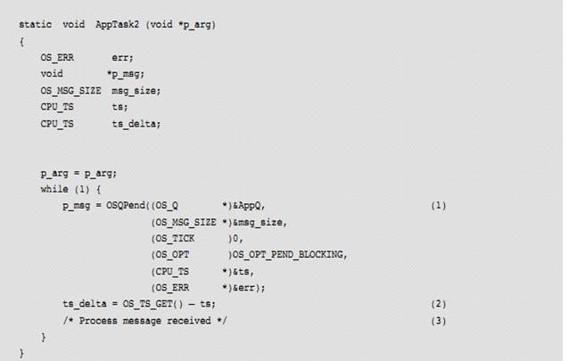
L3-7��2) ����������Ϣ���� AppQ ����һ����Ϣ��Ϊ��˵���� �������з��͵���һ�� void* 1����ʵ������Ϣ�а����ŵ���һ����ַ���ڴ��ַ�������ĵ�ַ������������Ҫ�����͵ĵ�ַ��
L3-7(2) The task then sends a message
to another task using the message queue AppQ. In this case, the example shows a
fixed message ��1,�� but the message could have consisted of the address of a
buffer, the address of a function, or whatever would need to be sent.
L3-7 ��3��������ȴ�һ���ź������������Ҫ�����ѱ���������ռ�õ���Դ��APPTaskStart1()�ȴ���� mutex ���ͷš��ڶ�������Ϊ��ȴ�ʱ�ޣ���ʱ��Ϊ��λ���� 0 ʱ�ͻ�һֱ�ȴ���ȥ��
L3-7(3) The task then waits on the
mutual exclusion semaphore since it needs to access a shared resource with
another task. If the resource is already owned by another task, AppTask1() will
wait forever for the mutex to be released by its current owner. The forever
wait is specified by passing 0 as the second argument of the call.
L3-7��4���� OSMutexPend()�����ˣ��ͱ���������ռ�������������Դ��������Դ�����DZ��������顢������IO �ȡ�
L3-7(4) When OSMutexPend() returns,
the task owns the resource and can therefore access the shared resource. The
shared resource may be a variable, an array, a data structure, an I/O device,
etc.
L3-7��5�����������ɶԹ�����Դ��ʹ�ã���������� OSMutexPost() �ͷ���� mutex��
L3-7(5) When the task is done with
the shared resource, it must call OSMutexPost() to release the mutex.
L3-8��1������#2 ��ʼִ�У����ȴ���Ϣ����
AppQ �е���Ϣ,�����������ȴ���ȥ��Ϊ����������Ϊ 0����ζ�����ȴ���
L3-8(1) Task #2 starts by waiting for
messages to be sent through the message queue AppQ. The task waits forever for
a message to be received because the third argument specifies an infinite
timeout.
��Ϣ�ķ����ߺͽ����߶�����֪�������Ϣ������������Ϣ��������Ϣ�Ĵ�С����"msg_size"��"p_msg"�ǵ��øú����ص���Ϣ��ַ��ָ���ڴ�����"msg_size"�а���������ڴ����Ĵ�С��
When
the message is received p_msg will contain the message (i.e., a pointer to
��something��). Both the sender and receiver must agree as to the meaning of the
message. The size of the message received is saved in ��msg_size��. Note that
��p_msg�� could point to a buffer and ��msg_size�� would indicate the size of this
buffer.
�����յ���Ϣʱ��"ts"�а���������Ϣ������ʱ��ʱ�����ʱ���
��ֵ��ȡ��Ӳ����ʱ����ʱ�����һ��
32 λ�������ֵ��
Also,
when the message is received, ��ts�� will contain the timestamp of when the
message was sent. A timestamp is the value read from a fairly fast free-running
timer. The timestamp is typically an unsigned 32-bit (or more) value.
L3-8��2�������Ϣ��ʲôʱ���͵ģ��û����ܲ��������������Ϣ���õ�ʱ�䡣��ȡ���ڵ�ʱ�������ȥ��Ϣ������ʱ��ʱ�������ע�⣬��Ϣ������ʱ���ȴ���Ϣ��������ܲ����������յ���Ϣ����Ϊ ISR ��������ȼ���������Ҫ�����С�
L3-8(2) Knowing when the message was
sent allows the user to determine how long it took this task to get the message.
Reading the current timestamp and subtracting the timestamp of when the message
was sent allows users to know how long it took for the message to be received.
Note that the receiving task may not get the message immediately since ISRs or
other higher-priority tasks might execute before the receiver gets to run.
L3-8��3���������յ�����Ϣ��
L3-8(3) Proceed with processing the
received message.
4���ٽ��
�ٽ�δ��룬Ҳ�����ٽ�����һ�β��ɷָ�Ĵ��롣uC/OS-III �а����˺ܶ��ٽ�δ��롣����ٽ�ο��ܱ��жϣ���ô����Ҫ���ж��Ա����ٽ�Ρ�����ٽ�ο��ܱ��������ϣ���ô��Ҫ�������������ٽ�Ρ�
A
critical section of code, also called a critical region, is code that needs to
be treated indivisibly. There are many critical sections of code contained in
��C/OS-III. If a critical section is accessible by an Interrupt Service Routine
(ISR) and a task, then disabling interrupts is necessary to protect the
critical region. If the critical section is only accessible by task level code,
the critical section may be protected through the use of a preemption lock.
uC/OS-III �е��ٽ�εı������������� ISR �ж���Ϣ�Ĵ�����ʽ
�� �� �� �� �� 9 �� �� �� �� �� �� �� �� ��OS_CFG_ISR_POST_DEFERRED_EN
����Ϊ 0���� OS_CFG.H�����ڽ� �� ��
�� �� ֮ ǰ uC/OS-III �� �� �� �� �� ���
OS_CFG_ISR_POST_DEFERRED_EN ����Ϊ 1���ڽ��������ٽ��֮ǰ��ص�������
Within
��C/OS-III, the critical section access method depends on which ISR post method
is used by interrupts (see Chapter 9, ��Interrupt Management�� on page 157). If
OS_CFG_ISR_POST_DEFERRED_EN is set to 0 (see OS_CFG.H) then ��C/OS-III will
disable interrupts when accessing internal critical sections. If
OS_CFG_ISR_POST_DEFERRED_EN is set to 1 then ��C/OS-III will lock the scheduler
when accessing most of its internal critical sections.
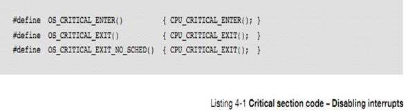
uC/OS-III ������һ�������ٽ�εĺ���������ٽ�εĺꡣ
��C/OS-III
defines one macro for entering a critical section and two macros for leaving:
OS_CRITICAL_ENTER������
OS_CRITICAL_EXIT������
OS_CRITICAL_EXIT_NO_SCHED����
��Щ�� uC/OS-III ���ڲ��꣬���ܱ��û�������á�Ȼ�����������Ҫ�������Լ�������ٽ�Ρ�����ĵ�ʮ����"��Դ����"��
These
macros are internal to ��C/OS-III and must not be invoked by the application
code. However, if you need to access critical sections in your application
code, consult Chapter 13, ��Resource Management�� on page 209.
���� OS_CFG_ISR_POST_DEFERRED_EN Ϊ 0 ���ڽ����ٽ��֮ǰ uC/OS-III ����жϣ����뿪�ٽ��֮���жϡ�{������˵�� CPU �Ĵ�����ָ���� CPU ���д����Ķ���Ĵ���}
When
setting OS_CFG_ISR_POST_DEFERRED_EN to 0, ��C/OS-III will disable interrupts
before entering a critical section and re-enable them when leaving the critical
section.
OS_CRITICAL_ENTER()���� uC/CPU�� ��CPU_CRITICAL_ENTER()
��Ȼ �� �� �� CPU_SR_Save() ��
CPU_SR_Save()���û��д�����ڱ��浱ǰ CPU �Ĵ��������жϡ��Ĵ���ֵ������Ϊ��cpu_sr���ı������ڵ����߶�ջ��
OS_CRITICAL_ENTER()
invokes the ��C/CPU macro CPU_CRITICAL_ENTER() that, in turn, calls
CPU_SR_Save(). CPU_SR_Save() is a function typically written in assembly language
that saves the current interrupt disable status and then disables interrupts.
The saved interrupt disable status is returned to the caller and in fact, it is
stored onto the caller��s stack in a variable called ��cpu_sr��.
OS_CRITICAL_EXIT() �� OS_CRITICAL_EXIT_NO_SCHED()
�������uC/CPU ��
�� CPU_CRITICAL_EXIT() ��CPU_CRITICAL_EXIT()���� CPU_SR_Restore()��CPU_SR_Restore�����ָ�������Ĵ���ֵ�� CPU �Ĵ�����Ҳ����
OS_CRITICAL_ENTER()����ǰ��״̬��
OS_CRITICAL_EXIT()
and OS_CRITICAL_EXIT_NO_SCHED() both invoke the ��C/CPU macro CPU_CRITICAL_EXIT(),
which maps to CPU_SR_Restore(). CPU_SR_Restore() is passed the value of the
saved ��cpu_sr�� variable to re-establish interrupts the way they were prior to
calling OS_CRITICAL_ENTER().
���͵ĺ�������б� 4-1 ��ʾ
The typical
code for the macros is shown in Listing 4-1.
4-1-1 �������ж�ʱ��
uC/CPU �ṩ�˲������ж�ʱ��Ĺ��ܡ�ͨ������ CPU_CFG.H �е�CPU_CFG_TIME_MEAS_INT_DIS_EN Ϊ 1 ���øù��ܡ�
��C/CPU
provides facilities to measure the amount of time interrupts are disabled. This
is done by setting the configuration constant CPU_CFG_TIME_MEAS_INT_DIS_EN to 1
in CPU_CFG.H.
ÿ�ι��ж�ǰ��ʼ���������жϺ�����������������ܱ����� 2 ������IJ���ֵ�������ܵĹ��ж�ʱ�䣬ÿ���������һ�ι��жϵ�ʱ�䡣��ˣ��û����Ը�������Ĺ��ж�ʱ���������Ż���
The
measurement is started each time interrupts are disabled and ends when
interrupts are re-enabled. The measurement keeps track of two values: a global
interrupt disable time, and an interrupt disable time for each task. Therefore,
it is possible to know how long a task disables interrupts, enabling the user
to better optimize their code.
ÿ������Ĺ��ж�ʱ�������ı����ʱ������ OS_TCB����� OS_CPU.C �е� OSTaskSwHook()�͵ڰ���"�������л�"����{�ҽ��������л��ֳ��������֣����ı��桢��������}
The
per-task interrupt disable time is saved in the task��s OS_TCB during a context
switch (see OSTaskSwHook() in OS_CPU_C.C and described in Chapter 8, ��Context
Switching�� on page 147).
ʱ����Ŀ��Ƶ�Ԫλ�� CPU_TS �С�ʱ��������ʾ����� CPU �����ʡ����磬��� CPU ����Ϊ 1MHz��ʱ���������Ϊ 1MHz����ôCPU_TS �ķֱ���Ϊ
1 �롣
The
unit of measure for the measured time is in CPU_TS (timestamp) units. It is
necessary to find out the resolution of the timer used to measure these
timestamps. For example, if the timer used for the timestamp is incremented at
1 MHz then the resolution of CPU_TS is 1 microsecond.
��Ȼ������Ĺ��ж�ʱ�仹�����˲���ʱ���ĵĶ���ʱ�䡣Ȼ������������ʱ����ʱ�����ʵ���ϵĹ��ж�ʱ�䡣
Measuring
the interrupt disable time obviously adds measurement artifacts and thus
increases the amount of time the interrupts are disabled. However, as far as
the measurement is concerned, measurement overhead is accounted for and the
measured value represents the actual interrupt disable time as if the
measurement was not present.
���ж�ʱ�����������ָ��ٶȡ��ڴ�����ٶ��кܴ�Ĺ�ϵ������������£�Ӳ�������Ӧ�����ڴ�ķ����ٶȣ�����Ӱ������ϵͳ���ܵġ�
Interrupt
disable time is obviously greatly affected by the speed at which the processor
accesses instructions and thus, the memory access speed. In this case, the
hardware designer might have introduced wait states to memory accesses, which
affects overall performance of the system. This may show up as unusually long
interrupt disable times.
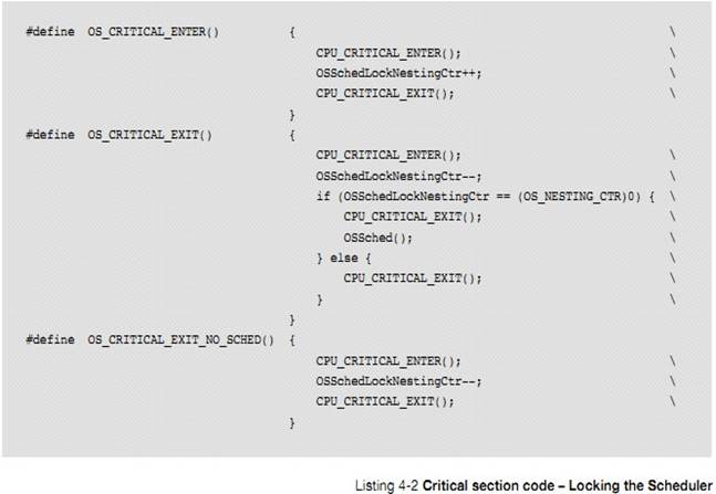
������ OS_CFG_ISR_POST_DEFERRED_EN Ϊ 1 ʱ���ڽ����ٽ��ǰ uC/OS-III ����ס���������˳��ٽ�κ�����������
When
setting OS_CFG_ISR_POST_DEFERRED_EN to 1, ��C/OS-III locks the scheduler before
entering a critical section and unlocks the scheduler when leaving the critical
section.
OS_CRITICAL_ENTER()���� OSSchedLockNestingCtr��������������������һ�������������Ƿ����ı������������Ϊ 0 �������������{����Ϊ��������Ƕ��ֵ����ʾ�����������˼�����}
OS_CRITICAL_ENTER()
simply increments OSSchedLockNestingCtr to lock the scheduler. This is the
variable the scheduler uses to determine whether or not the scheduler is
locked.
It
is locked when the value is non-zero.
OS_CRITICAL_EXIT()��OSSchedLockNestingCtr �ݼ�����������������{��������Ƕ��ֵ����Ϊ 0 ʱ���ͻ���õ�����}
OS_CRITICAL_EXIT()
decrements OSSchedLockNestingCtr and when the value reaches zero, invokes the
scheduler.
OS_CRITICAL_EXIT_NO_SCHED() Ҳ �� �� OSSchedLockNestingCtr
��ֵ����ͬ���ǵ���ֵ��Ϊ 0 ʱ�������õ�������
OS_CRITICAL_EXIT_NO_SCHED()
also decrements OSSchedLockNestingCtr, but does not invoke the scheduler when
the value reaches zero.
4-2-1 ������������ʱ��
uC/OS-III �ṩ�˲�����������ʱ��Ĺ��ܣ�ͨ������ OS_CFG.H �е� OS_CFG_SCHED_LOCK_TIME_MEAS_EN Ϊ 1 ������
��C/OS-III
provides facilities to measure the amount of time the scheduler is locked. This
is done by setting the configuration constant OS_CFG_SCHED_LOCK_TIME_MEAS_EN to
1 in OS_CFG.H.
����������ǰ������ʼ�������������������������õ�����ֵΪ:�ܵ���������ʱ�䣬ÿ���������������ʱ�䡣��ˣ��û�����֪��ÿ���������������ʱ�䣬�����ݴ��Ż����롣
The
measurement is started each time the scheduler is locked and ends when the
scheduler is unlocked. The measurement keeps track of two values: a global
scheduler lock time, and a per-task scheduler lock time. It is therefore
possible to know how long each task locks the scheduler allowing the user to
better optimize code.
ÿ���������������ʱ�����������л�ʱ����������� OS_TCB����� OS_CPU_C.C �е� OSTaskSwHook()�͵ڰ��¡��������л�������
The
per-task scheduler lock time is saved in the task��s OS_TCB during a context
switch (see OSTaskSwHook() in OS_CPU_C.C and described in Chapter 8, ��Context
Switching�� on page 147).
��õ���������ʱ�仹��������ʱ�������ӵ�ʱ�䡣���������ʱ�������������ʱ���ȷֵ��
Measuring
the scheduler lock time adds measurement artifacts and thus increases the
amount of time the scheduler is actually locked. However, measurement overhead
is accounted for and the measured value represents the actual scheduler lock
time as if the measurement was not present.
�� 4-1 չʾ�� uC/OS-III ijЩ����µĽϳ��ٽ�Ρ��˽���Щ���ݻ�����û����� uC/OS-III ���ٽ�Ρ�
Table
4-1 shows several ��C/OS-III features that have potentially longer critical
sections. Knowledge of these will help the user decide whether to direct
��C/OS-III to use one critical section over another.
�� 4-1 ���жϻ���������
|
����
|
ԭ��
|
|
������������ͬ���ȼ�
Multiple tasks at the same priority
|
�� uC/OS-III ��һ����Ҫ���ܣ�����������������ȼ������һ�����ٽ�Ρ�Ȼ�������������������ͬ���ȼ�ʱ���ж���ʱ���С����ʱ�����ù��жϷ��������ٽ�Ρ�
Although this is an important
feature of ��C/OS-III, multiple tasks at the same priority create longer
critical sections. However, if there are only a few tasks at the same
priority, interrupt latency would
be relatively small. If
multiple tasks are not created at the same priority, use the interrupt
disable method.
|
|
�¼���־������½� 14
��ͬ����
|
����������ȴ���ͬ���¼���������Щ������Ҫ�ܶദ��ʱ�䣬�ͻ�������ٽ�Ρ�������ٵ������ڵȴ��¼����ٽ�λ�̣ܶ���ô����ʹ�ù��жϵķ��������ٽ�Ρ�
If multiple tasks
are waiting on different events, going through all of the tasks waiting for
events requires a fair amount of processing time, which means longer critical
sections. If only a few tasks (approximately one to five) are waiting on an
event flag group, the critical section would be short enough to use the
interrupt disable method.
|
|
����ͬʱ�ȴ���
������
����½� 16
|
����ͬʱ�ȴ���������� uC/OS-III �ṩ�ĺܸ��ӵĹ��ܣ�����Ҫ�ܳ����ٽ�Ρ�����������Ƽ�ʹ�ùص������ķ�����
Pending on multiple
objects is probably the most complex feature provided by ��C/OS-III, requiring
interrupts to be disabled for fairly long periods of time should the
interrupt disable method be selected. If pending on multiple objects, it is
highly recommended that the user select the scheduler-lock method. If the
application does not use this feature, the interrupt disable method is an
alternative.
|
|
�㲥��Ϣ
|
uC/OS-III �ڴ����㲥��Ϣʱ�������������ٽ�Ρ�
��C/OS-III disables interrupts while
processing a post to multiple
tasks in a broadcast. When not using the broadcast option, you can use the
interrupt disable method.
|
uC/OS-III �л��õ��ٽ�Σ��ù��ж� (OS_CFG.H ������
OS_CFG_ISR_POST_DEFERRED_EN Ϊ 0)������������������OS_CFG_ISR_POST_DEFERRED_EN Ϊ 1��ʵ�ֱ����ٽ�εĹ��ܡ�
��C/OS-III
needs to access critical sections of code, which it protects by either
disabling interrupts (OS_CFG_ISR_POST_DEFERRED_EN set to 0 in OS_CFG.H), or locking
the scheduler (OS_CFG_ISR_POST_DEFERRED_EN set to 1 in OS_CFG.H).
�û�������ʹ����Щ���룺The application code must not use:
OS_CRITICAL_ENTER() OS_CRITICAL_EXIT() OS_CRITICAL_EXIT_NO_SCHED()
�� �� �� �� �� CPU_CFG.H �� ��CPU_CFG_TIME_MEAS_INT_DIS_EN
Ϊ 1 ʱ��uC/CPU ���������ܵĹ��ж�ʱ���ÿ������Ĺ��ж�ʱ�䡣
When
setting CPU_CFG_TIME_MEAS_INT_DIS_EN in CPU_CFG.H, ��C/CPU measures the maximum
interrupt disable time. There are two values available, one for the global
maximum and one for each task.
�� �� �� �� �� OS_CFG.H �� ��OS_CFG_SCHED_LOCK_TIME_MEAS_EN
Ϊ 1 ʱ��uC/OS-III ����������ܵ���������ʱ���ÿ��������������ʱ�䡣
When
setting OS_CFG_SCHED_LOCK_TIME_MEAS_EN to 1 in OS_CFG.H, ��C/OS-III will measure
the maximum scheduler lock time.
5���������
ʵʱӦ����һ�㽫�������Ϊ�������ÿ��������Ҫ�ǿɿ��ġ�ʹ�� uC/OS-III �������ɵؽ��������⡣����Ҳ�����̣߳��Ǽij��� CPU
�У����κ�ʱ��ֻ����һ������ִ�С�
The
design process of a real-time application generally involves splitting the work
to be completed into tasks, each responsible for a portion of the problem.
��C/OS-III makes it easy for an application programmer to adopt this paradigm. A
task (also called a thread) is a simple program that thinks it has the Central
Processing Unit (CPU) all to itself. On a single CPU, only one task can execute
at any given time.
uC/OS-III ֧�ֶ������Ҷ���������û�����ƣ���������ȡ���ڴ������ڴ�Ĵ�С(RAM)������������������ռ�� CPU �Ĺ��̡�
��C/OS-III
supports multitasking and allows the application to have any number of tasks.
The maximum number of task is actually only limited by the amount of memory
(both code and data space) available to the processor. Multitasking is the
process of scheduling and switching the CPU between several tasks (this will be
expanded upon later).
CPU �и����㷨�л���������������˸о������ж�� CPU �����У���������� CPU�����������������ģ�黯Ӧ�ã�������Ҫ�Ĺ���֮һ���ܰ�������Ա�������ӵ�ʵʱ��Ӧ�á�
The
CPU switches its attention between several sequential tasks. Multitasking
provides the illusion of having multiple CPUs and, actually maximizes the use
of the CPU. Multitasking also helps in the creation of modular applications.
One of the most important aspects of multitasking is that it allows the
application programmer to manage the complexity inherent in real-time
applications.
��Ҳʹ����������ƺ�ά����
Application
programs are typically easier to design and maintain when multitasking is used.
�������ڼ�����롢������������㡢ѭ�����ơ���ʾ������ť�ͼ��̡�������ϵͳ�����ȡ���ЩӦ���п���ֻ��������������ЩӦ����Ҳ���ܰ����ϰٸ������������ಢ����ζ������ж�û����ж���Ч����������Ӧ�õ���Ҫ������Ĺ���ҲҪ����Ӧ����ơ�һ���������ֻ��Ҫ�������룬Ȼ����Щ������ܾ���Ҫ������ʮ�����ˡ�
Tasks
are used for such chores as monitoring inputs, updating outputs, performing computations,
control loops, update one or more displays, reading buttons and keyboards,
communicating with other systems, and more. One application may contain a
handful of tasks while another application may require hundreds. The number of
tasks does not establish how good or effective a design may be, it really
depends on what the application (or product) needs to do. The amount of work a
task performs also depends on the application. One task may have a few
microseconds worth of work to perform while another task may require tens of
milliseconds.
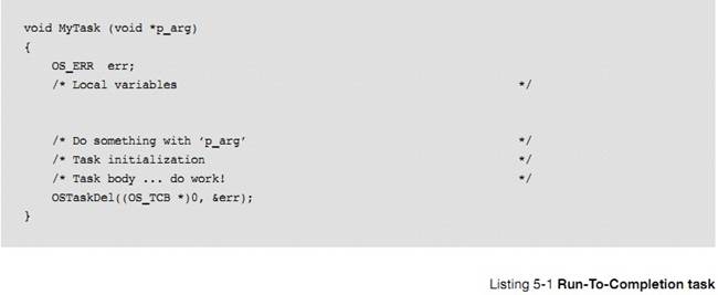
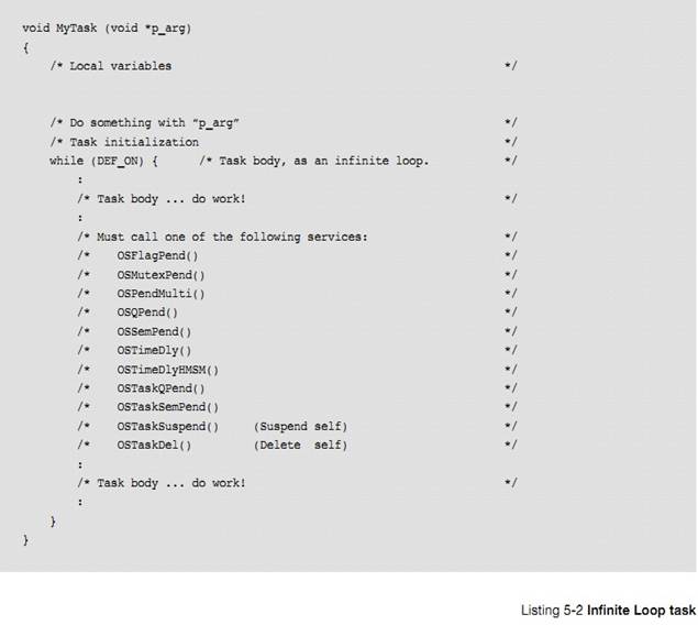
���������� C �������� 2 �����͵�����:����һ��(�б� 5-1)������ѭ�����б� 5-2�����ڴ����Ƕ��ʽϵͳ�У�����ͨ��������ѭ���ġ��������� C �������������Dz��� return �ġ�
Tasks
look like just any other C function except for a few small differences. There
are two types of tasks: run-to-completion (Listing 5-1) and infinite loop
(Listing 5-2). In most embedded systems, tasks typically take the form of an
infinite loop. Also, no task is allowed to return as other C functions can.
Given that a task is a regular C function, it can declare local variables.
�������һ��ִ��ʱ���ᴫ��һ������"p_arg"������һ��ָ�� void ��ָ�롣���ڱ����ĵ�ַ���ṹ���ַ�����ߺ����ĵ�ַ�ȡ������Ҫ�����Դ��������ͬ������ʹ����ͬ�Ĵ��루��ͬ�����壩���������в�ͬ�����н����
When
a ��C/OS-III task begins executing, it is passed an argument, p_arg. This
argument is a pointer to a void. The pointer is a universal vehicle used to
pass your task the address of a variable, a structure, or even the address of a
function, if necessary. With this pointer, it is possible to create many
identical tasks, that all use the same code (or task body), but, with different
run-time characteristics.
���磬4 ���첽���ж˿��и��Ե�����Ȼ�����������ʵ�����Ƕ����ģ�ֻ�Ǹ����� 4 �ζ��ѣ���Щ������Խ���ͨ��ָ��һ�������������ݵĽṹ�壨�粨���ʡ�IO �˿ڵ�ַ���ж������ŵȣ���
For
example, one may have four asynchronous serial ports that are each managed by
their own task. However, the task code is actually identical. Instead of
copying the code four times, create the code for a ��generic�� task that receives
a pointer to a data structure, which contains the serial port��s parameters
(baud rate, I/O port addresses, interrupt vector number, etc.) as an argument. In
other words, instantiate the same task code four times and pass it different
data for each serial port that each instance will manage
ֻ����һ�ε��������ʱ����ͨ������ OSTaskDel()ɾ���Լ�����������ʹϵͳ�е����������١����������У�������Ե���
uC/OS-III �ṩ�Ĵֺ����������������Ҫ��ɵĹ��ܡ�
A
run-to-completion task must delete itself by calling OSTaskDel(). The task
starts, performs its function, and terminates. There would typically not be too
many such tasks in the embedded system because of the overhead associated with
��creating�� and ��deleting�� tasks at run-time. In the task body, one can call
most of ��C/OS-III��s functions to help perform the desired operation of the
task.
�� uC/OS-III �У������� C ���Ժ������ǵ��û�����Ժ������ú������ÿ��ܱ��������ͬʱ���á�һ��������ĺ��������о�̬�����Լ�ȫ�ֱ������DZ�������uC/OS-III �ṩ�����ֱ�����������
With
��C/OS-III, call either C or assembly language functions from a task. In fact,
it is possible to call the same C function from different tasks as long as the
functions are reentrant. A reentrant function is a function that does not use
static or otherwise global variables unless they are protected (��C/OS-III
provides mechanisms for this) from multiple access.
��Ƕ��ʽϵͳ��ͨ��ʹ������ѭ����������ΪӦ�����кܶ���Ҫ�ظ��Ĺ��������磬��ȡ����ֵ��������ʾ�����Ʋ����ȣ������Dz�ͬ�� C ������һ�����棨C ����������
while(1)�� for(;;)ʵ����ͬ�Ĺ��ܣ����������
uC/OS-III ����������������������\
If
shared C functions only use local variables, they are generally reentrant
(assuming that the compiler generates reentrant code). An example of a
non-reentrant function is the famous strtok() provided by most C compilers as
part of the standard library. This function is used to parse an ASCII string
for ��tokens.�� The first time you call this function, you specify the ASCII string
to parse and what constitute tokens. As soon as the function finds the first
token, it returns. The function ��remembers�� where it was last so when called
again, it can extract additional tokens, which is clearly non-reentrant.
The
use of an infinite loop is more common in embedded systems because of the
repetitive work needed in such systems (reading inputs, updating displays,
performing control operations, etc.). This is one aspect that makes a task
different than a regular C function. Note that one could use a ��while (1)�� or
��for (;;)�� to implement the infinite loop, since both behave the same. The one
used is simply a matter of personal preference. At Micrium, we like to use
��while (DEF_ON)��. The infinite loop must call a ��C/OS-III service (i.e., function)
that will cause the task to wait for an event to occur. It is important that
each task wait for an event to occur, otherwise the task would be a true
infinite loop and there would be no easy way for other tasks to execute. This
concept will become clear as more is understood regarding ��C/OS-III.
��
�� �� �� �� ʱ һ �� ʱ �� �� �� �� OSTimeDly() �� �� OSTimeDlyHSM()�������磬Ӧ������Ҫÿ 100ms ɨ�����һ�Ρ�����������£���ʱ 100ms Ȼ����������Ƿ��м������£�Ȼ��ִ����Ӧ�IJ�����
The
event the task is waiting for may simply be the passage of time (when
OSTimeDly() or OSTimeDlyHMSM() is called). For example, a design may need to
scan a keyboard every 100 milliseconds. In this case, simply delay the task for
100 milliseconds then see if a key was pressed on the keyboard and, possibly
perform some action based on which key was pressed. Typically, however, a
keyboard scanning task should just buffer an ��identifier�� unique to the key
pressed and use another task to decide what to do with the key(s) pressed.
ͬ���ģ�����ȴ����¼���������̫�����������͵İ�������������£��������� OS???Pend()��������������ʽ����ĺ�������һ����������ɣ�������ݰ����ݽ�����һ��������
Similarly,
the event the task is waiting for could be the arrival of a packet from an
Ethernet controller. In this case, the task would call one of the OS???Pend()
calls (pend is synonymous with wait). The task will have nothing to do until
the packet is received. Once the packet is received, the task processes the
contents of the packet, and possibly moves the packet along a network stack.
ֵ��ע����ǣ������ڵȴ��¼�ʱ��������ռ�� CPU��
It��s
important to note that when a task waits for an event, it does not consume CPU
time.
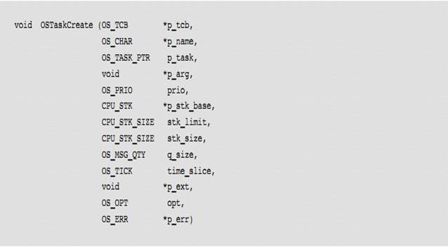
uC/OS-III ��Ҫͨ�����ú��� OSTaskCreate() ��������OSTaskCreate()������ԭ��������ʾ��
Tasks
must be created in order for ��C/OS-III to know about tasks. Create a task by
simply calling OSTaskCreate(). The function prototype for OSTaskCreate() is
shown below:
���� OSTaskCreate()�����������Լ����IJ�������ڸ�¼ A�����⣬����һ������ʱ����Ϊ�����һ�� TCB��һ����ջ��һ�����ȼ�������һЩ��������ͼ 5-1
A complete
description of OSTaskCreate() and its arguments is provided in Appendix A,
����C/OS-III API Reference Manual�� on page 375. However, it is important to
understand that a task needs to be assigned a Task Control Block (i.e., TCB), a
stack, a priority and a few other parameters which are initialized by
OSTaskCreate(), as shown in Figure 5-1.
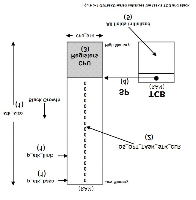
F5-1 �� 1 ������
OSTaskCreate() ʱ������Ϊ����ջ�Ļ���ַ��p_stk_base������ջ���������ƣ���ջ��С�ȡ�
F5-1(1) When calling OSTaskCreate(),
one passes the base address of the stack (p_stk_base) that will be used by the
task, the watermark limit for stack growth (stk_limit) which is expressed in
number of CPU_STK entries before the stack is empty, and the size of that stack
(stk_size), also in number of CPU_STK elements.
F5-1 �� 2 �� ��
OSTaskCreate() �� �� �� 12 �� �� �� �� �� ΪOS_OPT_TASK_STK_CHK|OS_OPT_TASK_STK_CLR��uC/OS-III�����ʼ����ջ����Ϊȫ 0��
F5-1(2) When specifying
OS_OPT_TASK_STK_CHK + OS_OPT_TASK_STK_CLR in the opt argument of OSTaskCreate(),
��C/OS-III initializes the task��s stack with all zeros.
F5-1��3��uC/OS-III ������ CPU �Ĵ������ݲ�����ش��������ջ�Ķ�������ʹ���������л�����ʵ�֡�
F5-1(3) ��C/OS-III then initializes
the top of the task��s stack with a copy of the CPU registers in the same
stacking order as if they were all saved at the beginning of an ISR. This makes
it easy to perform context switches as we will see when discussing the context
switching process. For illustration purposes, the assumption is that the stack
grows from high memory to low memory, but the same concept applies for CPUs
that use the stack in the reverse order.
F5-1��4����ջָ�� SP ��������� TCB �С�
F5-1(4) The new value of the stack
pointer (SP) is saved in the TCB. Note that this is also called the
top-of-stack.
F5-1��5��TCB ���������ֶλᱻ��ֵ���������ȼ���������������״̬���ڲ���Ϣ���С��ڲ��ź����ȡ�
F5-1(5) The remaining fields of the
TCB are initialized: task priority, task name, task state, internal message
queue, internal semaphore, and many others.
�������������һЩ������ OS_CPU_C.C �еĺ�����
OSTaskCreateHook()��TCB ����ָ��ָ�����������������չӦ�á����磬���Դ�ӡ���´����� TCB ���ݵ�ij�նˣ����ڵ��ԣ���
Next,
a call is made to a function that is defined in the CPU port,
OSTaskCreateHook() (see OS_CPU_C.C). OSTaskCreateHook() is passed the pointer
to the new TCB and this function allows you (or the port designer) to extend
the functionality of OSTaskCreate(). For example, one could printout the
contents of the fields of the newly created TCB onto a terminal for debugging
purposes.
Ȼ������ŵ������б������������"�����б�"����uC/OS-III
���õ����������л������ȼ���ߵ�����
The
task is then placed in the ready-list (see Chapter 6, ��The Ready List�� on page
123) and finally, if multitasking has started, ��C/OS-III will invoke the
scheduler to see if the created task is now the highest priority task and, if
so, will context switch to this new task.
������Ե��� uC/OS-III �ṩ�ĺ������ر�ģ�һ��������Դ�������������
OSTaskCreate()����ֹͣ���ָ���������(����OSTaskSuspned()�� OSTaskResume())���ύ�ź�����������������Ϣ�����������ṩ������Դ�ȡ����仰˵��������ֻ�������ڡ��ȴ��¼�����
The
body of the task can invoke other services provided by ��C/OS-III. Specifically,
a task can create another task (i.e., call OSTaskCreate()), suspend and resume
other tasks (i.e., call OSTaskSuspend() and OSTaskResume() respectively), post
signals or messages to other tasks (i.e., call OS??Post()), share resources
with other tasks, and more. In other words, tasks are not limited to only make ��wait
for an event�� function calls.
ͼ 5-2 չʾ��������������Դ�ĵ���ϵ��
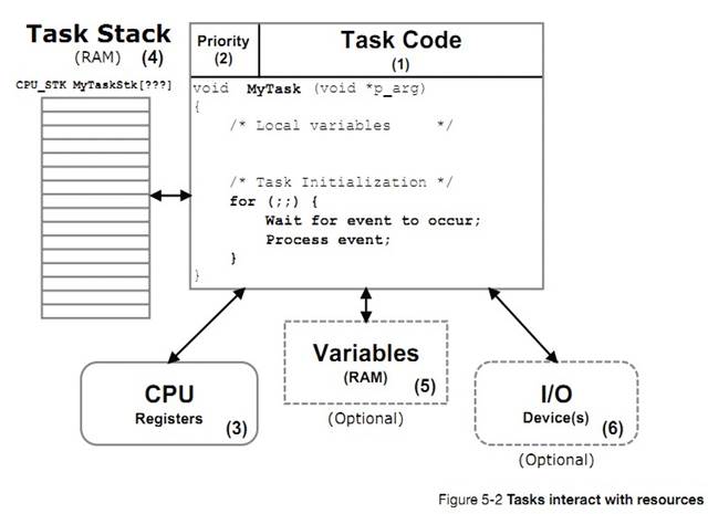
F5-2��1����������Ҫ�IJ��������Ĵ��롣����ǰ���ᵽ�ģ�����Ĵ��뿴�������Ǹ� C ������������ʵ������ѭ���ķ�ʽ�����⣬���������з���ֵ��
F5-2(1) An important aspect of a task
is its code. As previously mentioned, the code looks like any other C function,
except that it is typically implemented as an infinite loop. Also, a task is
not allowed to return.
F5-2��2��ÿ��������Ҫ���趨һ�����ȼ���uC/OS-III �Ĺ����Ǿ����ĸ�����Ӧ��ռ�� CPU��һ��ģ�uC/OS-III ѡ��������������ȼ���ߵ��������С�
F5-2(2) Each task is assigned a
priority based on its importance in the application. ��C/OS-III��s job is to
decide which task will run on the CPU. The general rule is that ��C/OS-III will
run the most important ready-to-run task (highest priority).
�� uC/OS-III �У���ֵԽС���ȼ�Խ�ߡ�
With
��C/OS-III, a low priority number indicates a high priority. In other words, a
task at priority 1 is more important than a task at priority 10.
uC/OS-III �����û��ڱ���ʱ�������ȼ��ķ�Χ����� OS_CFG.H �ļ��е� OS_PRIO_MAX�������⣬uC/OS-III �������������ͬ���ȼ��ҶԸ������������ơ����磬uC/OS-III ���Ա�����Ϊӵ�� 64 �ֲ�ͬ���ȼ������������ü�ʮ��������ͬ���ȼ���������� 5-1�������������ȼ�����
��C/OS-III
supports a compile-time user configurable number of different priorities (see
OS_PRIO_MAX in OS_CFG.H). Thus, ��C/OS-III allows the user to determine the
number of different priority levels the application is allowed to use. Also,
��C/OS-III supports an unlimited number of tasks at the same priority. For
example, ��C/OS-III can be configured to have 64 different priority levels and
one can assign dozens of tasks at each priority level.
F5-2��3��ÿ������� CPU �Ĵ����������Լ����á����һ���������У���ô���ͻ�ռ����ʵ�ʵ� CPU��
F5-2(3) A task has its own set of CPU
registers. As far as a task is concerned, the task thinks it has the actual CPU
all to itself.
F5-2��4����Ϊ uC/OS-III ��һ����ռʽ�ںˣ�ÿ��������Ҫ���Լ��Ķ�ջ�ռ䡣��ջפ���� RAM ���������ڱ��������������Ƕ��ISR ��ַ�ȡ�
F5-2(4) Because ��C/OS-III is a
preemptive kernel, each task must have its own stack area. The stack always
resides in RAM and is used to keep track of local variables, function calls,
and possibly ISR (Interrupt Service Routine) nesting.
��ջ�ռ���Ա�����Ϊ��̬�ģ��ڱ���ʱ���䣩�����Ƕ�̬�ģ�����ʱ���䣩�����徲̬�Ķ�ջ������ʾ��������������֮��ġ�
Stack
space can be allocated either statically (at compile-time) or dynamically (at
run-time). A static stack declaration is shown below. This declaration is made
outside of a function.
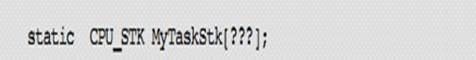
����
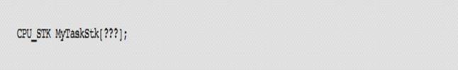
ע�⡰���������Ƕ�ջ�Ĵ�С�����������������ͨ�� C �������ṩ�Ķѹ������ܣ�malloc()����ջ�ռ���Ա���̬���䡣������ʾ�����ǣ������ע�洢��Ƭ����δ�����ɾ��������ڴ�����кܶ�洢��Ƭ���������ٷ���������ˡ���Ƕ��ʽϵͳ�ж�̬�ط����ջ�DZ������ģ����ǣ�һ����ջ����̬���䣬���Ͳ��ܱ����ա����仰˵��������Щ����Ҫ��ɾ��������̬�������ǵĶ�ջ��һ�ֺܺõĽ��������
Note
that ��???�� indicates that the size of the stack (and thus the array) depends on
the task stack requirements. Stack space may be allocated dynamically by using
the C compiler��s heap management function (i.e., malloc()) as shown below.
However, care must be taken with fragmentation. If creating and deleting tasks,
the process of allocating memory might not be able to provide a stack for the
task(s) because the heap will eventually become fragmented. For this reason,
allocating stack space dynamically in an embedded system is typically allowed
but, once allocated, stacks should not be deallocated. Said another way, it��s
fine to create a task��s stack from the heap as long as you don��t free the stack
space back to the heap.
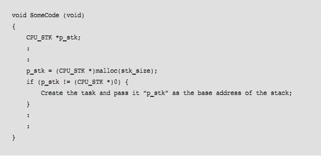
F5-2��5������Ҳ���Է���ȫ�ֱ�����Ȼ������Ϊ uC/OS-III ����ռʽ�ںˣ����б���ע��������ͬʱ����ȫ�ֱ�������������˵��ǣ� uC/OS-III �ṩ��һЩ���ܹ�����Щ������Դ�磨�ź�����mutex �ȣ���
F5-2(5) A task can also have access
to global variables. However, because ��C/OS-III is a preemptive kernel care
must be taken with code when accessing such variables as they may be shared
between multiple tasks. Fortunately, ��C/OS-III provides mechanisms to help with
the management of such shared resources
(semaphores,
mutexes and more).
F5-2��6������Ҳ���Է���һ������
IO �豸���������裩��
F5-2(6) A task may also have access
to one or more Input/Output (I/O) devices (also known as peripherals). In fact,
it is common practice to assign tasks to manage I/O devices.
��Щʱ����������ȼ����Զ����ġ����磬Ƕ��ʽϵͳ�е���Ҫ��Ӧ��Ӧ�ñ�����Ϊ�����ȼ���һЩ��ʾ������Ӧ�ñ�����Ϊ�����ȼ���Ȼ��������ʵʱϵͳ�ĸ����ԣ��ڴ�����������������ȼ��Dz��ܱ�����ȷ���ġ�����ϵͳ�У��������е���������Ҫ�ģ�����Ҫ������Ӧ�ñ�����Ϊ�����ȼ���
Sometimes
task priorities are both obvious and intuitive. For example, if the most
important aspect of the embedded system is to perform some type of control and
it is known that the control algorithm must be responsive then it is best to
assign the control task(s) a high priority while display and operator interface
tasks are assigned low priority. However, most of the time, assigning task
priorities is not so cut and dry because of the complex nature of real-time
systems. In most systems, not all tasks are considered critical, and
non-critical tasks should obviously be given low priorities.
An interesting
technique called rate monotonic scheduling (RMS) assigns task priorities based
on how often tasks execute. Simply put, tasks with the highest rate of
execution are given the highest priority. However, RMS makes a number of
assumptions, including:
�� All tasks are
periodic (they occur at regular intervals).
�� Tasks do not
synchronize with one another, share resources, or exchange data.
�� The CPU must always
execute the highest priority task that is ready to run. In other words,
preemptive scheduling must be used.
Given a set of n tasks that are
assigned RMS priorities, the basic RMS theorem states that all task hard
real-time deadlines are always met if the following inequality holds true:

Where Ei corresponds to
the maximum execution time of task i, and Ti corresponds to
the execution period of task i. In other
words, Ei/Ti corresponds to
the fraction of CPU time required to execute task i.
Table 5-1 shows
the value for size n(21/n �C 1) based on the
number of tasks. The upper bound for an infinite number of tasks is given by ln(2), or 0.693, which means
that meeting all hard real-time deadlines based on RMS, CPU use of all
time-critical tasks should be less than 70 percent!
Note that one
can still have (and generally does) non time-critical tasks in a system and
thus use close to 100 percent of the CPU��s time. However, using 100 percent of
your CPU��s time is not a desirable goal as it does not allow for code changes
and added features. As a rule of thumb, always design a system to use less than
60 to 70 percent of the CPU.
RMS says that
the highest rate task has the highest priority. In some cases, the highest rate
task might not be the most important task. The application dictates how to
assign priorities.
However, RMS is
an interesting starting point.
|
Number of Tasks
|
|
n(21/n-1)
|
|
1
|
1.00
|
|
|
2
|
0.828
|
|
|
3
|
0.779
|
|
|
4
|
0.756
|
|
|
5
|
0.743
|
|
|
:
|
:
|
|
|
:
|
:
|
|
|
:
|
:
|
|
|
Infinite
|
0.693
|
|
Table 5-1 Allowable CPU usage based on number of
tasks
��ջ�Ĵ�Сȡ���ڸ�����������趨��ջ��Сʱ�������Ҫ���ǣ����п��ܱ���ջ���õĺ������亯����Ƕ�ײ�������ؾֲ������Ĵ�С���жϷ����������Ҫ�Ŀռ䡣���⣬��ջ�������CPU�Ĵ���������������и�������ԪFPU�Ĵ����Ļ��������FPU�Ĵ�����Ƕ��ʽϵͳ��DZ������д�ݹ麯����
The
size of the stack required by the task is application specific. When sizing the
stack, however, one must account for the nesting of all the functions called by
the task, the number of local variables to be allocated by all functions called
by the task, and the stack requirements for all nested interrupt service
routines. In addition, the stack must be able to store all CPU registers and
possibly Floating-Point Unit (FPU) registers if the processor has a FPU. As a
general rule in embedded systems, avoid writing recursive code.
�����˹��ؼ����������Ҫ�Ķ�ջ�ռ��С����Ƕ�����п��ܱ����õĺ��������ӱ����ú��������еIJ����������������л�ʱ��CPU�Ĵ����ռ䣬�����л����ж�ʱ�����CPU�Ĵ����ռ䣨����CPU û�ж����Ķ�ջ���ڴ����жϣ������Ӵ���ISRs����Ķ�ջ�ռ䡣��������ȫ����ӣ��õ���ֵ����Ϊ��С������ռ䡣
It
is possible to manually figure out the stack space needed by adding all the
memory required by all function call nesting (1 pointer each function call for
the return address), plus all the memory required by all the arguments passed
in those function calls, plus storage for a full CPU context (depends on the
CPU), plus another full CPU context for each nested ISRs (if the CPU doesn��t
have a separate stack to handle ISRs), plus whatever stack space is needed by
those ISRs. Adding all this up is a tedious chore and the resulting number is a
minimum requirement.
��Ϊ���Dz����ܼ������ȷ�Ķ�ջ�ռ䡣ͨ�����ٳ���1.5��2.0��ȷ������İ�ȫ���С���������Ǽٶ����������е�ִ��·�߶�����֪������µģ������Dz�̫���ܵġ�����˵���������printf()���������ĺ����� printf()��������Ҫ�Ŀռ��Ǻ��Ѳ�û���˵���Dz�����֪���ġ�����������£��տ�ʼʱ����������һ���ϴ�Ķ�ջ�ռ䲢�������ʱ��ջ�ռ��ʵ��ʹ������{һ�㶼��ͨ�����������ö�ջ�����ʹ������Ȼ���1.5������Ϊ��ջ�ռ��С}
Most
likely one would not make the stack size that precise in order to account for
��surprises.�� The number arrived at should probably be multiplied by some safety
factor, possibly 1.5 to 2.0. This calculation assumes that the exact path of
the code is known at all times, which is not always possible. Specifically,
when calling a function such as printf() or some other library function, it
might be difficult or nearly impossible to even guess just how much stack space
printf() will require. In this case, start with a fairly large stack space and
monitor the stack usage at run-time to see just how much stack space is
actually used after the application runs for a while.
������/������ṩ�ĵ�����ӳ����Ϣ�Ǻ����õġ���ÿ�������У�����ӳ���ṩ�˺����������¶�ջʹ��������������ܹ��ȽϾ�ȷ������ÿ����������Ķ�ջ�ռ䡣��Ȼ����������һ��CPU�Ĵ����ռ䡢��һ��CPU�Ĵ����ռ䣨���CPUû�ж����Ŀռ䴦�� ISR�Ļ������ټ�����ЩISR��Ҫ�Ķ�ջ�ռ䡣
There
are really cool and clever compilers/linkers that provide this information in a
link map. For each function, the link map indicates the worst-case stack usage.
This feature clearly enables one to better evaluate stack usage for each task.
It is still necessary to add the stack space for a full CPU context plus,
another full CPU context for each nested ISR (if the CPU does not have a
separate stack to handle ISRs), plus whatever stack space is needed by those
ISRs. Again, allow for a safety net and multiply this value by some factor.
���Ϊ�˱�֤�ɿ������ٳ���һ��1.5���ҵ�ֵ���ڲ�Ʒ�Ŀ����Ͳ��ԽΣ�ͨ��������ʱ�õ�����������ջ��ʹ�������
Always
monitor stack usage at run-time while developing and testing the product as
stack overflows occur often and can lead to some curious behaviors. In fact,
whenever someone mentions that his or her application behaves ��strangely,��
insufficient stack size is the first thing that comes to mind.
1) Using an MMU or MPU
�����������MMU����MPU������ջ�Ƿ�����Ƿdz��ġ�
MMU��MPU��CPU���ϵ�����Ӳ����ʩ�����Լ��Ƿ����ʣ����������ͼ����δ���������ڴ�ռ�Ļ����ͻ�������档������MMU��MPU���DZ�����Ҫ���ܵġ�
Stack
overflows are easily detected if the processor has a Memory Management Unit
(MMU) or a Memory Protection Unit (MPU). Basically, MMUs and MPUs are special
hardware devices integrated alongside the CPU that can be configured to detect
when a task attempts to access invalid memory locations, whether code, data, or
stack. Setting up an MMU or MPU is well beyond the scope of this book.
2) Using a CPU with stack
overflow detection
һЩ����������һЩ��ջ������Ĵ�������CPU�Ķ�ջָ��С�ڣ�����ڣ�ȡ���ڶ�ջ��������������������Ĵ�����ֵʱ���쳣����ʱ�쳣���������Ҫȷ��δ�����ռ����İ�ȫ�����ܻᷢ�;�����û�����OS_TCB�е�.StkLimitPtr����Ϊ����Ŀ�����õ���ͼ5-3.��ջ���뱻�����㹻��Ŀռ䡣�ڴ��������£���ָ���ֵ�������ýӽ���&MYTaskStk[0]��
{�ٶ���ջ�ǴӸߵ�ַ���͵�ַ������}
Some
processors, however, do have simple stack pointer overflow detection registers.
When the CPU��s stack pointer goes below (or above depending on stack growth)
the value set in this register, an exception is generated and the exception
handler ensures that the offending code does not do further damage (possibly
issue a warning about the faulty code). The .StkLimitPtr field in the OS_TCB
(see Task Control Blocks) is provided for this purpose as shown in Figure 5-3.
Note that the position of the stack limit is typically set at a valid location
in the task��s stack with sufficient room left on the stack to handle the
exception itself (assuming the CPU does not have a separate exception stack).
In most cases, the position can be fairly close to &MyTaskStk[0].
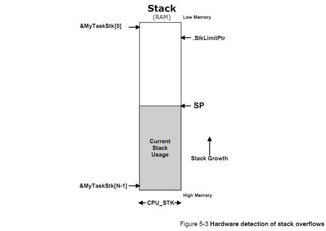
�ڴ����ѣ�
StkLimitPtr ��ֵȡ���� OSTaskCreate() �IJ���"stk_limit"������ʾ��
As a
reminder, the location of the .StkLimitPtr is determined by the ��stk_limit��
argument passed to OSTaskCreate(), when the task is created as shown below:
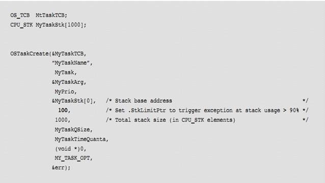
��Ȼ���� uC/OS-III ִ���������л���ʱ��StkLimitPtr ��ֵ�ᱻ�ı䡣���Ƿdz����ֵģ���Ϊ����ջ������Ĵ�����ֵ���ı�ʱ�轫�����ȱ�����Ϊ NULL��Ȼ��ı� CPU �Ķ�ջָ�룬���� TCB �� stkLimitPtr ֵ�浽��ջ���Ĵ����С�Ϊ�Σ����������������̣���ô�ڶ�ջָ����ջ������Ĵ����ı�ʱ�������жϾ��鷳�ˡ�ͨ�����ȸı��ջ������Ĵ���ָ��һ����ַ��ͨ����Ϊ NULL���Ӷ��ö�ջָ��������Ч�ġ�ע�⣬�����ڼٶ���ջ�ǴӸߵ�ַ���͵�ַ�����ģ���ջ��������ӵ����ߵĵ���Ҳ��һ���ġ�
Of
course, the value of .StkLimitPtr used by the CPU��s stack overflow detection
hardware needs to be changed whenever ��C/OS-III performs a context switch. This
can be tricky because the value of this register may need to be changed so that
it first points to NULL, then change the CPU��s stack pointer, and finally set
the value of the stack checking register to the value saved in the TCB��s
.StkLimitPtr. Why? Because if the sequence is not followed, the exception could
be generated as soon as the stack pointer or the stack overflow detection
register is changed. One can avoid this problem by first changing the stack
overflow detection register to point to a location that ensures the stack
pointer is never invalid (thus the NULL as described above). Note that I
assumed here that the stack grows from high memory to low memory but the
concept works in a similar fashion if the stack grows in the opposite
direction.
3) Software-based stack overflow detection
�� uC/OS-III ��һ�������л�����һ�������ʱ���������һ�� hook ���� OSTaskSwHook()���������û���չ�������л�ʱ�Ĺ��ܡ����ԣ����������û��Ӳ��֧��������ܣ��Ϳ����ڸ� hook ���������Ӵ�������ģ��ù��ܡ�
Whenever
��C/OS-III switches from one task to another, it calls a ��hook�� function
(OSTaskSwHook()), which allows the ��C/OS-III port programmer to extend the
capabilities of the context switch function. So, if the processor doesn��t have
hardware stack pointer overflow detection, it��s still possible to ��simulate��
this feature by adding code in the context switch hook function and, perform
the overflow detection in software.
�ر�ģ����л������� B ǰ��������⽫Ҫ������ CPU ��ջָ���ֵ�Ƿ������� B �� TCB ��StkLimitPtr
���ơ���Ϊ�������������ʱ��Ѹ�ٵ�������Ӧ������Ӧ������ StkLimitPtr ��ֵ������Զ��&MyTaskStk[0]����֤���㹻��������塣��ͼ 5-4��������ⲻ����Ӳ�����������Ч����Ҳ���Է�ֹ��ջ�����
Specifically,
before a task is switched in, the code should ensure that the stack pointer to
load into the CPU does not exceed the ��limit�� placed in .StkLimitPtr. Because
the software implementation cannot detect the stack overflow ��as soon�� as the
stack pointer exceeds the value of .StkLimitPtr, it is important to position
the value of .StkLimitPtr in the stack fairly far from &MyTaskStk[0], as
shown in Figure 5-4. A software implementation such as this is not as reliable
as a hardware-based detection mechanism but still prevents a possible stack
overflow. Of course, the .StkLimitPtr field would be set using OSTaskCreate()
as shown above but this time, with a location further away from
&MyTaskStk[0].
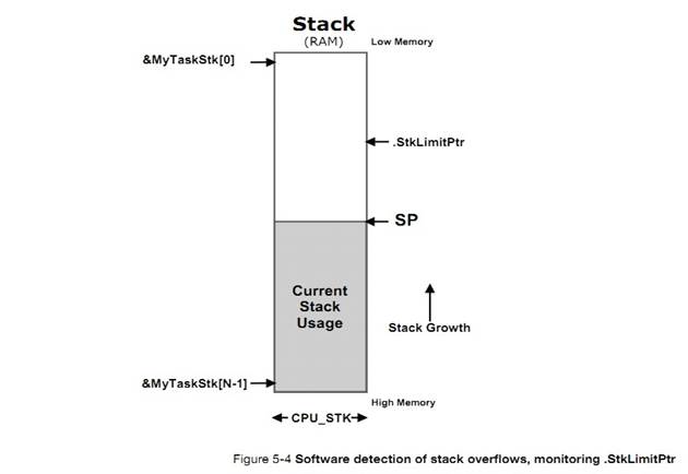
4) Counting the amount of free stack space
��һ�ַ�ֹ��ջ����ķ����Ƿ���Ŀռ�Զ���ڿ�����Ҫ�õ��ġ�Ȼ���������������ʱ�������õ�����ջ�ռ䡣��������ʵ�ֵġ����ȣ�������ʱ���ջ�����㡣Ȼ��ͨ��һ�������ȼ������������������ջ��ֵΪ 0 ���ڴ��С��
Another
way to check for stack overflows is to allocate more stack space than is
anticipated to be used for the stack, then, monitor and possibly display actual
maximum stack usage at run-time. This is fairly easy to do. First, the task
stack needs to be cleared (i.e., filled with zeros) when the task is created.
Next, a low priority task walks the stack of each task created, from the bottom
(&MyTaskStk[0]) towards the top, counting the number of zero entries.
������ֶ���Ϊ 0����ô����Ҫ��չ��ջ�Ĵ�С��Ȼ������ջΪ����Ӧ��С������һ�ַdz���Ч�ķ�����ע����ǣ������������кܳ���ʱ�����ö�ջ�ﵽ����Ҫ�����ֵ�����ͼ 5-5��uC/OS-III �ṩ��һ������OSTaskStkChk() ����ʵ��������㹦�ܡ���ʵ�ϣ����������OS_StatTask()����ͳ��ÿ������Ķ�ջʹ�������
When
the task finds a non-zero value, the process is stopped and the usage of the
stack can be computed (in number of bytes used or as a percentage). Then,
adjust the size of the stacks (by recompiling the code) to allocate a more
reasonable value (either increase or decrease the amount of stack space for
each task). For this to be effective, however, run the application long enough
for the stack to grow to its highest value. This is illustrated in Figure 5-5.
��C/OS-III provides a function that performs this calculation at run-time,
OSTaskStkChk() and in fact, this function is called by OS_StatTask() to compute
stack usage for every task created in the application (to be described later).
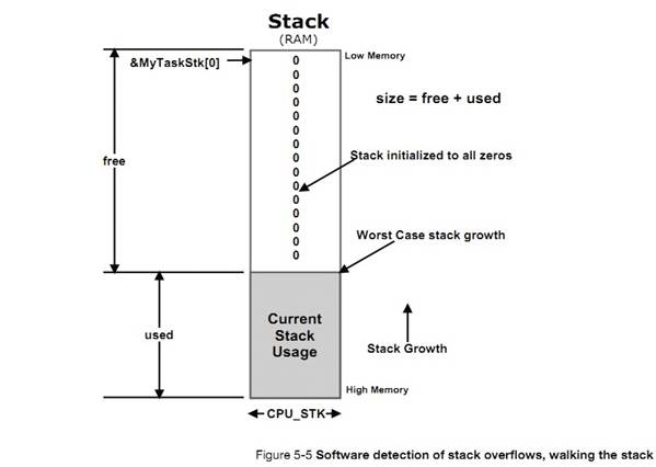
uC/OS-III �ṩ�˺ܶ���������صĺ�������Щ����������OS_TASK.C ���ҵ������Ƕ����� OSTask???()��ʽ�����ġ�
��C/OS-III
provides a number of task-related services to call from the application. These
services are found in OS_TASK.C and they all start with OSTask???(). The type
of service they perform groups task-related services:
|
����
|
����
|
|
��ͨ��
General
|
OSTaskCteate()
OSTaskDel()
OSTaskChangePrio()
OSTaskRegSet()
OSTaskRegGet()
OSTaskSuspend()
OSTaskResume()
OSTaskTimeQuantaSet()
|
|
�������
Signaling a Task
|
OSTaskSemPend()
OSTaskSemPost()
OSTaskSemPendAbort()
|
|
����������Ϣ
Sending Messages to a Task
|
OSTaskQPend()
OSTaskQPost()
OSTaskQPendAbort()
OSTaskQFlush()
|
uC/OS-III ������غ����Ľ��������¼
A��
5-5-1 ����״̬
���û��Ĺ۵������������������ 5 ��״̬����ͼ 5-6��չʾ������״̬���ת����ϵ��{����״̬������״̬������״̬������״̬���ж�״̬}
From
a ��C/OS-III user point of view, a task can be in any one of five states as
shown in Figure 5-6. Internally, ��C/OS-III does not need to keep track of the
dormant state and the other states are tracked slightly differently. This will
be discussed after a discussion on task states from the user��s point of view.
Figure 5-6 also shows which ��C/OS-III functions are used to move from one state
to another. The diagram is actually simplified as state transitions are a bit
more complicated than this.
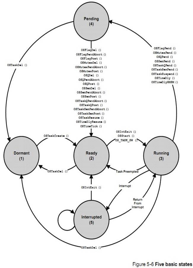
F5-6��1����������״̬������פ�����ڴ浫δ�� uC/OS-III ʹ�ܡ�
F5-6(1) The Dormant state corresponds
to a task that resides in memory but has not been made available to ��C/OS-III.
ͨ������ OSTaskCreate()���� uC/OS-III ����������������Ǵ����� ROM �ġ�����Ҫ�� OSTaskCreate()����֪ͨ uC/OS-III ��������������Ϣ��
A
task is made available to ��C/OS-III by calling a function to create the task,
OSTaskCreate(). The task code actually resides in code space but ��C/OS-III
needs to be informed about it.
��������ʹ������ˣ���Ҫ���� OSTaskDel()ɾ��������OSTaskDel()ʵ���ϲ���ɾ������Ĵ��룬ֻ���������پ���ʹ��CPU ���ʸ���ѡ�
When
it is no longer necessary for ��C/OS-III to manage a task, call the task delete
function, OSTaskDel(). OSTaskDel() does not actually delete the code of the
task, it is simply not eligible to access the CPU.
F5-6��2������״̬������������ȼ�����������ھ����б��С������б��жԾ�������ĸ���û�����ơ�
F5-6(2) The Ready state corresponds
to a ready-to-run task, but is not the most important task ready. There can be
any number of tasks ready and ��C/OS-III keeps track of all ready tasks in a
ready list (discussed later). This list is sorted by priority.
F5-6��3���������е�������Ϊ����״̬���ڵ� CPU �У��κ�ʱ��ֻ����һ���������С�
F5-6(3) The most important
ready-to-run task is placed in the Running state. On a single CPU, only one
task can be running at any given time.
��Ӧ�ó������ OSStart() ���ߵ��� OSIntExit() ���ߵ��� OS_TASK_SW()ʱ uC/OS-III �Ӿ���������ѡ�����ȼ���ߵ�����ȥ���С�
The
task selected to run on the CPU is switched in by ��C/OS-III from the ready
state when the application code calls OSStart(), or when ��C/OS-III calls either
OSIntExit() or OS_TASK_SW().
����ǰ�����ᵽ�ģ���Щʱ���������ȴ�ijЩ�¼����������¼���δ����ʱ������ͻᱻ����Ϊ����״̬��
As
previously discussed, tasks must wait for an event to occur. A task waits for
an event by calling one of the functions that brings the task to the pending
state if the event has not occurred.
F5-6��4������״̬���������ڹ����б����Ա��������ڵȴ�ijЩ�¼��ķ������ȴ���ʱ�������Dz���ռ�� CPU �ġ��¼�����ʱ��������ᱻ�ŵ����������С�����������£��������е�������ܻᱻ��ռ�����Żؾ����б��������� uC/OS-III ѡ�����ȼ���ߵ�����ȥ���С����仰˵������µ��������ȼ���ߣ���ô���ͻᱻ�������С���ע�⣬���� OSTaskSuspend()��������������ֹͣ���С���Щʱ�����
OSTaskSuspend()����Ϊ�˵ȴ�ij���¼��ķ��������ǵȴ���һ��������� OSTaskResume()�����ָ��������
F5-6(4) Tasks in the Pending state
are placed in a special list called a pend-list (or wait list) associated with
the event the task is waiting for. When waiting for the event to occur, the
task does not consume CPU time. When the event occurs, the task is placed back
into the ready list and ��C/OS-III decides whether the newly readied task is the
most important ready-to-run task. If this is the case, the currently running
task will be preempted (placed back in the ready list) and the newly readied
task is given control of the CPU. In other words, the newly readied task will
run immediately if it is the most important task.
Note
that the OSTaskSuspend() function unconditionally blocks a task and this task
will not actually wait for an event to occur but in fact, waits until another
task calls OSTaskResume() to make the task ready to run.
F5-6��5�����жϷ������жϻ��������ִ�е�����ȥ���� ISR��ISR �п�����ijЩ����ȴ����¼���һ����˵���ж�����֪ͨ����ijЩ�¼��ķ�����������������ʵ�ʵ���Ӧ������ISR ����Խ��Խ�ã�ʵ����Ӧ�жϵIJ���Ӧ�ñ������������Ա����� uC/OS-III ������Щ������ISR ��ֻ��������һЩ�ύ����(OSFlagPost()��OSQPost()��OSSemPost()��OSTaskQPost()��OSTaskSemPost())������OSMutexPost()����Ϊ mutex ֻ�����������ġ�
F5-6(5)
Assuming that CPU interrupts are enabled, an interrupting device will suspend
execution of a task and execute an Interrupt Service Routine (ISR). ISRs are
typically events that tasks wait for. Generally speaking, an ISR should simply
notify a task that an event occurred and let the task process the event. ISRs
should be as short as possible and most of the work of handling the interrupting
devices should be done at the task level where it can be managed by ��C/OS-III.
ISRs are only allowed to make ��Post�� calls (i.e., OSFlagPost(), OSQPost(),
OSSemPost(), OSTaskQPost() and OSTaskSemPost()). The only post call not allowed
to be made from an ISR is OSMutexPost() since mutexes, as will be addressed
later, are assumed to be services that are only accessible at the task level.
����ͼ��ʾ��������һ���жϿ��Ա���һ���ж�����ռ��������ж�Ƕ�ף������������֧���ж�Ƕ�ס�Ȼ������������������ж�Ƕ���Ǻ����������ջ����ġ�
As
the state diagram indicates, an interrupt can interrupt another interrupt. This
is called interrupt nesting and most processors allow this. However, interrupt
nesting easily leads to stack overflow if not managed properly.
uC/OS-III
һֱ���������״̬��ͼ 5-7����ʵ�ϣ���Щ������һ����������ʽ������ÿ������� TCB �С�ͼС�����е���ֵ��ʾ�������״̬��ÿ���������� 8 ��״̬����
��� OS.H ��OS_TASK_STATE_???��ͼ�в���������̬����Ϊ uC/OS-III ��֧������̬��������ж��Լ��жϵ�Ƕ���и���Ľ��⡣
Internally,
��C/OS-III keeps track of task states using the state machine shown in Figure
5-7. The task state is actually maintained in a variable that is part of a data
structure associated with each task, the task��s TCB. The task state diagram was
referenced throughout the design of ��C/OS-III when implementing most of
��C/OS-III��s services. The number in parentheses is the state number of the task
and thus, a task can be in any one of eight (8) states (see OS.H,
OS_TASK_STATE_???). Note that the diagram does not keep track of a dormant
task, as a dormant task is not known to ��C/OS-III. Also, interrupts and
interrupt nesting is tracked differently as will be explained further in the
text.
���״̬ͼ���������⺯��������״̬��Ĺ�ϵ��
This
state diagram should be quite useful to understand how to use several functions
and their impact on the state of tasks. In fact, I��d highly recommend that the
reader bookmark the page of the diagram.
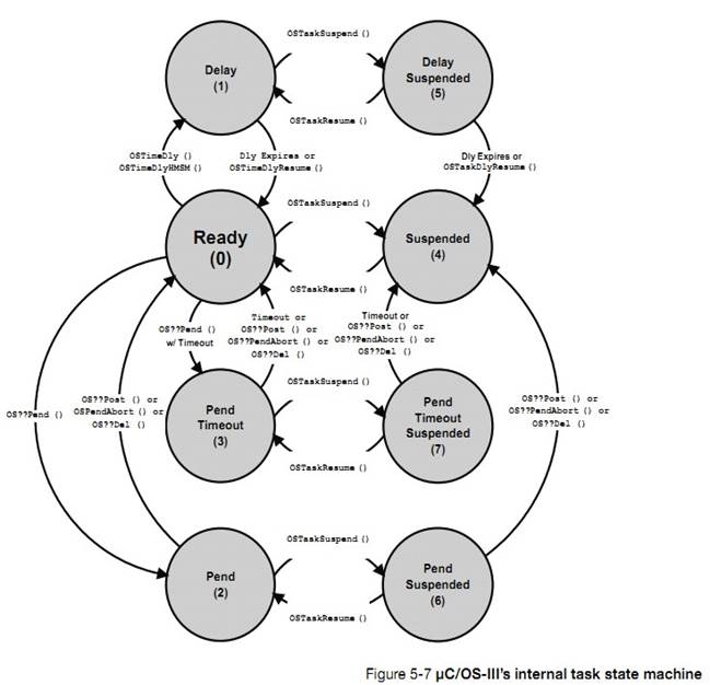
F5-7��1��״̬ 0 ��ʾ�����Ѿ�������ÿ�������ڱ�����֮ǰ�����봦�ھ���״̬��
F5-7(1) State 0 occurs when a task is
ready to run. Every task ��wants�� to be ready to run as that is the only way it
gets to perform their duties.
F5-7��2���������ͨ������ OSTimeDly()���� OSTimeDlyHMSM() �ȴ�������������������ʱɾ��ʱ��ͨ������
OSTimeDlyResume()���������תΪ����״̬��
F5-7(2) A task can decide to wait for
time to expire by calling either OSTimeDly() or OSTimeDlyHMSM(). When the time
expires or the delay is cancelled (by calling OSTimeDlyResume()), the task
returns to the ready state.
F5-7��3���������ͨ�����ù�������OSFlagPend()��OSMutexPend()�� OSQPend��OSSemPend��OSTaskQPend()��OSTaskSemPend()���ȴ�ij�¼��ķ��������¼�����ʱ��������ɾ�������߱���һ������ȡ���ȴ�ʱ���ȴ�ֹͣ��
F5-7(3) A task can wait for an event
to occur by calling one of the pend (i.e., wait) functions (OSFlagPend(),
OSMutexPend(), OSQPend(), OSSemPend(), OSTaskQPend(), or OSTaskSemPend()), and
specify to wait forever for the event to occur. The pend terminates when the
event occurs (i.e., a task or an ISR performs a ��post��), the awaited object is
deleted or, another task decides to abort the pend.
F5-7��4����ǰ����˵��������Եȴ��¼�������������Ҳ���Ա����õȴ�����ʱ�䡣��������ʱ�����¼�û�з���������Ҳ�ᱻ��Ϊ����״̬����֪ͨ��������ǵȴ���ʱ��������ġ�{����������һ�����ں���ִ�н��������ţ����Բ鿴�������֪����������α�������}
F5-7(4) A task can wait for an event
to occur as indicated, but specify that it is willing to wait a certain amount
of time for the event to occur. If the event is not posted within that time,
the task is readied, then the task is notified that a timeout occurred. Again,
the pend terminates when the event occurs (i.e., a task or an ISR performs a
��post��), the object awaited is deleted or, another task decides to abort the
pend.
F5-7
��5��������ͣ�Լ����߱�����������ͣ��ͨ������OSTaskSuspend()������ͣ�е�����ֻ��ͨ������ OSTaskResume()���ָ���
F5-7(5) A task can suspend itself or
another task by calling OSTaskSuspend(). The only way the task is allowed to
resume execution is by calling OSTaskResume(). Suspending a task means that a task
will not be able to run on the CPU until it is resumed by another task.
F5-7��6��һ����ʱ�е�����Ҳ���Ա�������������Ϊֹͣ������������£�Ч���ᱻ���ӡ����仰˵����ʱ�豻ִ�С�ֹͣ״̬�豻�����������Żᱻִ�С�
F5-7(6) A delayed task can also be
suspended by another task. In this case, the effect is additive. In other
words, the delay must complete (or be resumed by OSTimeDlyResume()) and the
suspension must be removed (by another task which would call OSTaskResume()) in
order for the task to be able to run.
F5-7��7��һ������״̬�е�����Ҳ���ܱ�������������Ϊֹͣ��ͬ���ģ�Ч���ᱻ���ӡ��¼�������ֹͣ״̬���Ƴ�������Żᱻִ�С�
F5-7(7) A task waiting on an event to
occur may be suspended by another task. Again, the effect is additive. The
event must occur and the suspension removed (by another task) in order for the
task to be able to run. Of course, if the object that the task is pending on is
deleted or, the pend is aborted by another task, then one of the above two
condition is removed. The suspension , however, must be explicitly removed.
F5-7��8��������Եȴ��¼��ķ����������Ը����趨һ�����ޡ�ͬ���ģ���Ҳ���ܱ���Ϊֹͣ��Ч���ǵ��ӵġ������Ƴ�ֹͣ״̬���¼�������ȴ��¼���ʱ������Żᱻִ�С�
F5-7(8) A task can wait for an event,
but only for a certain amount of time, and the task could also be suspended by
another task. As one might expect, the suspension must be removed by another
task (or the same task that suspended it in the first place), and the event
needs to either occur or timeout while waiting for the event.
5-5-2 ������ƿ� TCB
������ƿ��DZ� uC/OS-III ����ά�������һ���ṹ�塣ÿ�����������Լ��� TCB��uC/OS-III �� RAM �з���
TCB�������� uC/OS-III �ṩ����������صĺ�������
OSTask???()��ʽ������ʱ������� TCB ��ַ��ᱻ�ṩ���ú�����TCB �Ľṹ������ OS.H �У����б� 5-3 ��ʾ���� OS.H �д�������ע�͵ģ���
A
task control block (TCB) is a data structure used by kernels to maintain
information about a task. Each task requires its own TCB and, for ��C/OS-III,
the user assigns the TCB in user memory space (RAM). The address of the task��s
TCB is provided to ��C/OS-III when calling task-related services (i.e.,
OSTask???() functions). The task control block data structure is declared in
OS.H as shown in Listing 5-3. Note that the fields are actually commented in
OS.H, and some of the fields are conditionally compiled based on whether or not
certain features are desired. Both are not shown here for clarity.
TCB
�е�һЩ�������Ը��ݾ���Ӧ�ý��вü����û�����Ӧ�÷�����Щ���������䲻�ܸ������ǣ������仰˵��TCB �еı���ֻ�ܱ� uC/OS-III ���ʡ�
Also,
it is important to note that even when the user understands what the different
fields of the OS_TCB do, the application code must never directly access these
(especially change them). In other words, OS_TCB fields must only be accessed
by ��C/OS-III and not the code.
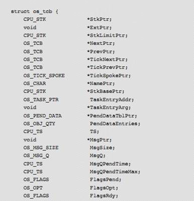
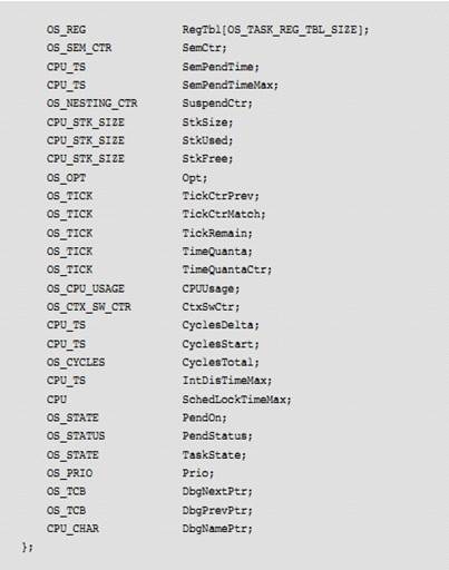
.StrPtr
��������а�����ָ��ǰ�����ջ��ָ�롣uC/OS-III ����ÿ���������Լ��Ķ�ջ�ҶԸö�ջ�Ĵ�Сû�����ơ� .StkPtr ������OS_TCB ����������Ψһһ����Ҫ��������������ʵģ������������л����ֵĴ��룩����ˣ�������������ڽṹ���еĵ�һ�����û�����Ը����ط��ʵ�����ʹ���� TCB �ṹ���е�ƫ����Ϊ 0����
This
field contains a pointer to the current top-of-stack for the task. ��C/OS-III allows
each task to have its own stack and each stack can be any size. .StkPtr should
be the only field in the OS_TCB data structure accessed from assembly language
code (for the context-switching code). This field is therefore placed as the
first entry in the structure making access easier from assembly language code
(it will be at offset zero in the data structure).
.ExtPtr
��������ж�����ָ���û�������չ TCB�������Ҫ����ָ�롣���ָ��Ҳ�����ڱ�������Է��ʵġ�
This
field contains a pointer to a user-definable pointer to extend the TCB as
needed. This pointer is easily accessible from assembly language.
.StkLimitPtr
��������б����˶�ջ����ʱ�����Ƶ�ַ�������ڵ���OSTaskCreate()ʱ���ݵIJ���"stk_limit"����Щ��������Ӳ���Ĵ��������Զ��ؼ�Ⲣȷ����ջ��������������������û����ЩӲ����ʩ����ջ������������ģ�⡣Ȼ��������ģ�ⲻ��Ӳ���ɿ�������������û�б��õ�����ô�ڵ��� OSTaskCreate() ʱ��������"stk_limit"Ϊ 0����� 5-3��
The
field contains a pointer to a location in the task��s stack to set a watermark
limit for stack growth and is determined from the value of the ��stk_limit��
argument passed to OSTaskCreate(). Some processors have special registers that
automatically check the value of the stack pointer at run-time to ensure that
the stack does not overflow. .StkLimitPtr may be used to set this register
during a context switch. Alternatively, if the processor does not have such a
register, this can be ��simulated�� in software. However, it is not as reliable
as a hardware solution. If this feature is not used then the value of
��stk_limit�� can be set to 0 when calling OSTaskCreate(). See also section 5-3
��Detecting Task Stack Overflows�� on page 87).
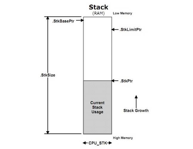
.NextPtr ��.PrevPtr
��Щָ�����ھ���������˫��������˫������������ TCB ���б����ܸ���ر��������ɾ����
These
pointers are used to doubly link OS_TCBs in the ready list. A doubly linked
list allows OS_TCBs to be quickly inserted and removed from the list.
.TickNextPtr ��.TickPrevPtr
��Щָ�����ڹ��������˫��������˫������������ TCB ���б����ܸ���ر��������ɾ����
These
pointers are used to doubly link OS_TCBs in the list of tasks waiting for time
to expire or to timeout from pend calls. Again, a doubly linked list allows
OS_TCBs to be quickly inserted and removed from the list.
.TickSpokePtr
���ָ�����ڱ�ʾʱ����ת���ַ���ʱ����ת���ڵھ��¡��жϹ���������ϸ���ܡ�
This
pointer is used to know which spoke in the ��tick wheel�� the task is linked to.
The tick wheel will be described in ��Chapter 9, ��Interrupt Management�� on page
157.��
.NamePtr
���ָ��������������֡������ֵ�����dz������ڵ��ԣ���Ϊ�������Ѻõ���ʾÿ�������Ӧ�� TCB ��ַ�������ֵ��ַ������� ROM������Գ������������� RAM��
This
pointer allows a name (an ASCII string) to be assigned to each task. Having a
name is useful when debugging, since it is user friendly compared to displaying
the address of the OS_TCB. Storage for the ASCII string is assumed to be in
user space in code memory (ASCII string declared as a const) or in RAM.
.StkBasePtr
{�����ջ���ɸߵ�ַ��͵�ַ����}
���ָ��ָ���������ջ�Ļ���ַ������Ļ���ַͨ����������פ����ջ��������ڴ��ַ�������ջ�Ķ��壺
This
field points to the base address of the task��s stack. The stack base is
typically the lowest address in memory where the stack for the task resides. A
task stack is declared as follows:
CPU_STK MyTaskStk[???];
�����ջ�ռ������ CPU_STK �������ͣ�"������"��Ҫ����Ķ�ջ�Ĵ�С�����Ļ���ַͨ����&MyTaskStk[0]��
CPU_STK
is the data type you must use to declare task stacks and ??? is the size of the
stack associated with the task. The base address is always &MyTaskStk[0].
.TaskEntryAddr
��������а���������������ڵ�ַ������ǰ���ᵽ�ģ����������·�ʽ������
This
field contains the entry address of the task. As previously mentioned, a task is
declared as shown below and this field contains the address of MyTask.
void
MyTask(void *p_arg)��
.TaskEntryAtg
��������ǵ������һ������ʱ���ݸ�����IJ��������������ᵽ�ģ��������ֵ�ᴫ�� p_arg��
This
field contains the value of the argument that is passed to the task when the
task starts. As previously mentioned, a task is declared as shown below and
this field contains the value of p_arg.
.PendDataTblPtr
uC/OS-III
��������ͬʱ�������ź�������Ϣ���С����ָ��ָ���˰�����Щ���������ı���
��C/OS-III
allows the task to pend on any number of semaphores or message queues simultaneously.
This pointer points to a table containing information about the pended objects.
.PendDataEntries
���������.PendDataTblPtr һ��������ʾ��ͬһʱ��ij����ȴ����¼�����
This
field works with the .PendDataTblPtr, indicating the number of objects a task
is pending on at the same time.
.TS
��������洢���������ȴ��¼����ֵ�ʱ�����������ָ�ִ��ʱ��ʱ����ᱻ���ظ�����
This
field is used to store a ��time stamp�� of when an event that the task was
waiting on occurred. When the task resumes execution, this time stamp is
returned to the caller.
.MsgPtr
������Ϣ��������ʱ��������������˸���Ϣ�ĵ�ַ���ڱ���ʱʹ������Ϣ���з���(OS_CFG.H ������ OS_CFG_Q_EN Ϊ 1)��ʹ���������ڽ���Ϣ���У�OS_CFG.H ������ OS_CFG_TASK_Q_EN Ϊ 1������������ų����� TCB �У���Ȼ�ͻᱻ�ü���
When
a message is sent to a task, this field contains the message received. This
field only exists in a TCB if message queue services (OS_CFG_Q_EN is set to 1
in OS_CFG.H), or task message queue services, are enabled (OS_CFG_TASK_Q_EN is
set to 1 in OS_CFG.H) at compile time.
.MsgSize
������Ϣ��������ʱ�����������������Ϣ�Ĵ�С�����ֽ�Ϊ��λ������������������� TCB �У������Ϣ���з���(��
OS_CFG.H ������ OS_CFG_Q_EN Ϊ 1)����������з����� OS_CFG.H ������ OS_CFG_TASK_Q_EN Ϊ 1������ʱ��ʹ�ܵĻ���
When
a message is sent to a task, this field contains the size (in number of bytes)
of the message received. This field only exists in a TCB if message queue
services (OS_CFG_Q_EN is set to 1 in OS_CFG.H), or task message queue services,
(OS_CFG_TASK_Q_EN is set to 1 in OS_CFG.H) are enabled at compile time.
.MsgQ
uC/OS-III
��������� ISR ֱ�ӷ�����Ϣ������ʵ����Ҳ����Ϣ�����ڽ���ÿ������� TCB ���ˣ��������ʱ�� OS_CFG.H ������OS_CFG_TASK_Q_EN Ϊ 1����.MsgQ ������ OSTaskQ???()������
��C/OS-III
allows tasks or ISRs to send messages directly to tasks. Because of this, a
message queue is actually built into each TCB. This field only exists in a TCB
if task message queue services are enabled at compile time (OS_CFG_TASK_Q_EN is
set to 1 in OS_CFG.H). .MsgQ is used by the OSTaskQ???() services.
.MsgQPendTime
��������Ϣ�Ӵ����������������ʱ�䡣�� OSTaskQPost()������ʱ����ȡ��ǰ��ʱ�������������Ϣ�С���
OSTaskQPend()���յ������Ϣʱ����ȡ��ǰ��ʱ�����������Ϣ���ύʱ��ʱ����������ֵ��������������С����������� uC/Probe ���Թ۲����������ֵ��
This
field contains the amount of time for a message to arrive. When OSTaskQPost()
is called, the current time stamp is read and stored in the message. When
OSTaskQPend() returns, the current time stamp is read again and the difference
between the two times is stored in this variable. A debugger or ��C/Probe can be
used to indicate the time taken for a message to arrive by displaying this
field.
������ʱ���� OS_CFG.H �е� OS_CFG_TASK_PROFILE_EN Ϊ 1 ʱ�������������Ч��
This
field is only available if setting OS_CFG_TASK_PROFILE_EN to 1 in OS_CFG.H.
.MsgQPendTimeMax
��������б�������Ϣ��������ʱ������ֵ������.MsgQPendTime �ķ�ֵ�����ֵ���Ա� OSStatReset()��λ��
This
field contains the maximum amount of time it takes for a message to arrive. It
is a peak detector of the value of .MsgQPendTime. The peak can be reset by
calling OSStatReset().
�ڱ���ʱ���� OS_CFG.H �е�OS_CFG_TASK_PROFILE_EN Ϊ 1 ʱ�������������Ч��
This
field is only available if setting OS_CFG_TASK_PROFILE_EN to 1 in OS_CFG.H.
.FlagsPend
������ȴ��¼���־�飬��������������������ȴ��ı�־λ��������ʱ������ OS_CFG.H �е� OS_CFG_FLAG_EN Ϊ 1 ʱ�����������Ч��
When
a task pends on event flags, this field contains the event flags (i.e., bits)
that the task is pending on. This field only exists in a TCB if event flags
services are enabled at compile time (OS_CFG_FLAG_EN is set to 1 in OS_CFG.H).
.FlagsOpt
������ȴ��¼���־�飬��������������������ȴ��¼���־������͡��ڱ���ʱ������ OS_CFG.H �е� OC_CFG_FLAG_EN Ϊ 1 ʱ�����������Ч��
When
a task pends on event flags, this field contains the type of pend (pend on any
event flag bit specified in .FlagsPend or all event flag bits specified in
.FlagsPend). This field only exists in a TCB if event flags services are
enabled at compile time (OS_CFG_FLAG_EN is set to 1 in OS_CFG.H).
.FlagsRdy
��������������Ѿ����ύ���¼���־�飨�������ȴ��ģ������仰˵����������֪�����ĸ��¼���־������������ġ��ڱ���ʱ������ OS_CFG.H �е� OS_CFG_FLAG_EN Ϊ 1 ʱ�����������Ч��
This
field contains the event flags that were posted and that the task was waiting
on. In other words, it allows a task to know which event flags made the task
ready to run. This field only exists in a TCB if event flags services are
enabled at compile time (OS_CFG_FLAG_EN is set to 1 in OS_CFG.H).
.RegTbl[]
��������а����������"�Ĵ���"����ͬ��
CPU �Ĵ���������Ĵ������ڴ洢���� ID����������ȡ���Ҫע����������������������� OS_REG�������ڱ���ʱ����ġ����е�����Ĵ����������������������͡��ڱ���ʱ����
OS_CFG.H �е�����Ĵ��������С�� OS_CFG_TASK_REG_TBL_SIZE ���� 0 ʱ�������Ż���Ч��
This
field contains a table of ��registers�� that are task-specific. These registers
are different than CPU registers. Task registers allow for the storage of such
task-specific information as task ID, ��errno�� common in some software
components, and more. Task registers may also store task-related data that
needs to be associated with the task at run time. Note that the data type for
elements of this array is OS_REG, which can be declared at compile time to be
nearly anything. However, all registers must be of this data type. This field
only exists in a TCB if task registers are enabled at compile time
(OS_CFG_TASK_REG_TBL_SIZE is greater than 0 in OS_CFG.H).
.SemCtr
��������������ź����ļ���ֵ��ÿ������������ڽ��ź����� ISR �������������ͨ���ź����������������.SemCtr ���ڼ�¼��������˼��Ρ�.SemCtr �� OSTaskSem???()�б��õ���
This
field contains a semaphore counter associated with the task. Each task has its
own semaphore built-in. An ISR or another task can signal a task using this
semaphore. .SemCtr is therefore used to keep track of how many times the task
is signaled. .SemCtr is used by OSTaskSem???() services.
.SemPendTime
�б������ź����Ӳ��������������õ�ʱ�䡣�� OSTaskSemPost() �����ã���ǰ��ʱ�������ȡ���������ź����С���
OSTaskSemPend() �����յ��ź���ʱ����ǰ��ʱ�������ȡ����֮ǰ��ʱ����IJ�ֵ����������������������� uC/Probe ���Թ۲��������ֵ��
This
field contains the amount of time taken for the semaphore to be signaled. When
OSTaskSemPost() is called, the current time stamp is read and stored in the
OS_TCB (see .TS). When OSTaskSemPend() returns, the current time stamp is read
again and the difference between the two times is stored in this variable.
������OS_CFG.H �е� OS_CFG_TASK_PROFILE_EN Ϊ 1 ʱ�����Ż���Ч��
This
field can be displayed by a debugger or ��C/Probe to indicate how much time it
took for the task to be signaled.
.SemPendTimeMax
�������ź����Ӳ���������������ʱ������ֵ������.SemPendTime �Ƿ�ֵ�����Ե��� OSStatReset()��λ��������������� OS_CFG.H �е�
This
field contains the maximum amount of time it took for the task to be signaled.
It is a peak detector of the value of .SemPendTime. The peak can be reset by
calling OSStatReset().
OS_CFG_TASK_PROFILE_EN Ϊ 1 ʱ�����Ż���Ч��
This
field is only available if setting OS_CFG_TASK_PROFILE_EN to 1 in OS_CFG.H.
.SuspendCtr
��������� OSTaskSuspend()�� OSTaskResume()ʹ�ã����ڼ�¼����ֹͣ�Ĵ���������ֹͣ���Ա�Ƕ�ף���.SuspendCtr Ϊ 0 ʱ��������Ա�ִ�С�������ʱ���� OS_CFG.H �е�OS_CFG_TASK_SUSPEND_EN Ϊ 1 ʱ��������Ż���Ч��
This
field is used by OSTaskSuspend() and OSTaskResume() to keep track of how many
times a task is suspended. Task suspension can be nested. When .SuspendCtr is
0, all suspensions are removed. This field only exists in a TCB if task
suspension is enabled at compile time (OS_CFG_TASK_SUSPEND_EN is set to 1 in
OS_CFG.H).
.StkSize
��������б����˶�ջ�Ĵ�С���� CPU_STK Ϊ�������ͣ�����ջ�Ķ�������
This
field contains the size (in number of CPU_STK elements) of the stack associated
with the task. Recall that a task stack is declared as follows:
CPU_STK
MyTaskStk[???];
.StkSize
����???��ֵ��
.StkSize
is the value of ??? in the above array.
.StkUsed ��.StkFree
������ʱ��uC/OS-III ���Լ������ջ��ʵ��ʹ�����Ϳ�����������ͨ������
OSTaskStkChk()ʵ�ֵġ���ջʹ���������Ǽٶ���ջ�ڴ���ʱ����ʼ��������µġ����仰˵����
OS_TASK_OPT_STK_CLR �� OS_TASK_OPT_STK_CHK ��ʹ��ʱ��OSTaskCreate()������ʱ���ȳ�ʼ�������ջ�� RAM��{һ���ʼ�����ǽ���ջȫ�������}
��C/OS-III
is able to compute (at run time) the amount of stack space a task actually uses
and how much stack space remains. This is accomplished by a function called
OSTaskStkChk(). Stack usage computation assumes that the task��s stack is
��cleared�� when the task is created. In other words, when calling
OSTaskCreate(), it is expected that the following options be specified:
OS_TASK_OPT_STK_CLR and OS_TASK_OPT_STK_CHK. OSTaskCreate() will then clear all
the RAM used for the task��s stack.
uC/OS-III
�ṩ��һ������ OS_StatTask()�����������Լ��ÿһ������Ķ�ջʹ�������OS_StatTask()ͨ���������ڵ����ȼ��������������� CPU ����ʱ���С�OS_StatTask()�������������ÿ������� TCB �С������������ջ�����ʹ���������ֽ���ʽ�ļ���ֵ���Ϳ������������� OS_CFG.H �е�OS_CFG_STAT_TASK_STK_CHK_EN Ϊ 1 ʱ��������������Ч��
��C/OS-III
provides an internal task called OS_StatTask() that checks the stack of each of
the tasks at run-time. OS_StatTask() typically runs at a low priority so that
it does not interfere with the application code. OS_StatTask() saves the value
computed for each task in the TCB of each task in these fields, which represents
the maximum number of stack bytes used and the amount of stack space still
unused by the task. These fields only exist in a TCB if the statistic task is
enabled at compile time (OS_CFG_STAT_TASK_STK_CHK_EN is set to 1 in OS_CFG.H).
.Opt
������ʱ���ݸ� OSTaskCreate()�IJ���������������ĸ��ӹ��ܡ�
This field saves the ��options�� passed to OSTaskCreate()
when the task is created (see OS_TASK_OPT_??? in OS.H). Note that task options
are additive.
.TickCtrPrev
�� OSTimeDly()ѡ�� OS_OPT_TIME_PERIODIC ��ʽʱ���ñ���Ϊ OSTickCtr �ij�ֵ��
This field stores the previous value of OSTickCtr when
OSTimeDly() is called with the OS_OPT_TIME_PERIODIC option.
.TickCtrMatch
��������ʱһ��ʱ�䣬������ȴ��¼�������ʱ�ޡ�����ͻᱻ�ŵ���������С�����������У�����ȴ��Լ��� TickCtrMatch ֵ��ʱ������ֵ��OSTickCtr����ƥ�䡣ƥ�䷢��ʱ������ͻᱻ�Ƴ�������С�
When
a task is waiting for time to expire, or pending on an object with a timeout,
the task is placed in a special list of tasks waiting for time to expire. When
in this list, the task waits for .TickCtrMatch to match the value of the ��tick
counter�� (OSTickCtr). When a match occurs, the task is removed from that list.
.TickRemain
��������б���������ʱ��ʣ��ʱ��ֵ������ OS_TickTask() �б����㡣����ʱ��������Ǻ����õġ�
This
field is computed at run time by OS_TickTask() to compute the amount of time
(expressed in ��ticks��) left before a delay or timeout expires. This field is
useful for debuggers or run-time monitors for display purposes.
.TimeQuanta ��.TimeQuantaCtr
��������������ʱ����Ƭ�������������������ͬ�����ȼ�ʱ��.TimeQuanta ������ʱ��Ƭ���ȣ����ٸ�ʱ������.TimeQuantaCtr �б����˵�ǰʱ��Ƭ��ʣ��ȡ��������л���ʼʱ��.TimeQuanta ��ֵ����.TimeQuantaCtr��
These
fields are used for time slicing. When multiple tasks are ready to run at the
same priority, .TimeQuanta determines how much time (in ticks) the task will
execute until it is preempted by ��C/OS-III so that the next task at the same
priority gets a chance to execute. .TimeQuantaCtr keeps track of the remaining
number of ticks for this to happen and is loaded with .TimeQuanta at the
beginning of the task��s time slice.
.CPUUsage
������ CPU ��ʹ���ʣ�0 �� 100%�������DZ� OS_StatTask()��������ġ�����ʱ������ OS_CFG.H �е� OS_CFG_TASK_PROFILE_EN Ϊ 1 ʱ�ñ�����Ч��
This
field is computed by OS_StatTask() if OS_CFG_TASK_PROFILE_EN is set to 1 in
OS_CFG.H. .CPUUsage contains the CPU usage of a task in percent (0 to 100%).
.CtxSwCtr
�����˸�����ִ�еĴ���������ʱ���Բ鿴���������ֵ������ʱ���� OS_CFG_TASK_PROFILE_EN Ϊ 1 ʱ���������Ч��
This
field keeps track of how often the task has executed (not how long it has
executed).This field is generally used by debuggers or run-time monitors to see
if a task is executing (the value of this field would be non-zero and would be
incrementing). The field is enabled at compile time when OS_CFG_TASK_PROFILE_EN
is set to 1.
.CyclesDelta
���������л�ʱ�����㣬�������˵�ǰʱ����� CyclesStart �IJ�ֵ������ʱ����ͨ����֪���������ִ��ʱ�䡣������OS_CFG_TASK_PROFILE_EN
Ϊ 1 ʱ�ñ�����Ч��
.CyclesDelta
is computed during a context switch and contains the value of the current time
stamp (obtained by calling OS_TS_GET()) minus the value of .CyclesStart. This
field is generally used by debuggers or a run-time monitor to see how long a
task takes to execute. The field is enabled at compile time when
OS_CFG_TASK_PROFILE_EN is set to 1.
.CyclesStart
����������ڲ��������ִ��ʱ�䣬.CyclesStart ���������л�ʱ�����¡��������������л�ʱ��ʱ���(ͨ������ OS_TS_GET()���)��������ʱ���� OS_CFG_TASK_PROFILE_EN Ϊ 1 ʱ������Ч��
This
field is used to measure the execution time of a task. .CyclesStart is updated
when ��C/OS-III performs a context switch. .CyclesStart contains the value of
the current time stamp (it calls OS_TS_GET()) when a task switch occurs. This
field is generally used by debuggers or a run-time monitor to see how long a
task takes to execute. The field is enabled at compile time when
OS_CFG_TASK_PROFILE_EN is set to 1.
.CyclesTotal
��������� CyclesDelta ���ۼӣ������������˸�����ִ�е���ʱ�䡣�������������Ϊ
64 λ��ֹ�����ʹ��һ�� 64 λ�ı�������ȷ�� 1GHz �� CPU ��Լ���� 600 ����������Ȼ����Ҫ�������֧�� 64 λ���������͡�
This
field accumulates the value of .CyclesDelta, so it contains the total execution
time of a task. This is typically a 64-bit value because of the accumulation of
cycles over time. Using a 64-bit value ensures that we can accumulate CPU
cycles for almost 600 years even if the CPU is running at 1 GHz! Of course,
it��s assumed that the compiler supports 64-bit data types.
.IntDisTimeMax
��������б����˸�������жϵ����ʱ�䡣ʹ�������ǰ���� uC/CPU ֧�ֹ��ж�ʱ��IJ������������� OS_CFG.H �е�OS_CFG_TASK_PROFILE_EN Ϊ 1 �Ҷ����� CPU_CFG.H �е�CPU_CFG_TIME_MEAS_INT_DIS_EN ʱ��������Ч��{�� CPU_CFG.H ����ֻ�ҵ�
CPU_CFG_INT_DIS_MEAS_EN�������Ǻ����������˵��ֲ��ϸ��¹���}
This
field keeps track of the maximum interrupt disable time of the task. The field
is updated only if ��C/CPU supports interrupt disable time measurements. This field
is available only if setting OS_CFG_TASK_PROFILE_EN to 1 in OS_CFG.H and
��C/CPU��s CPU_CFG_TIME_MEAS_INT_DIS_EN is defined in DCPU_CFG.H.
.SchedLockTimeMax
�����˸������������������ʱ�䡣�������� OS_CFG.H �е�OS_CFG_TASK_PROFILE_EN Ϊ 1 ������OS_CFG_SCHED_LOCK_TIME_MEAS_EN Ϊ
1 ʱ��������Ч��
The
field keeps track of the maximum scheduler lock time of the task.
This
field is available only if you set OS_CFG_TASK_PROFILE_EN to 1 and
OS_CFG_SCHED_LOCK_TIME_MEAS_EN is set to 1 in OS_CFG.H.
.PendOn
�ñ�����ֵȡ����������α�������� OS.H �е�OS_TASK_PEND_ON_???����
This
field indicates upon what the task is pending and contains
OS_TASK_PEND_ON_???(see OS.H).
.PendStatus
���������������������״̬������� OS.H �е�OS_STATUS_PEND_??? )��{PendOn �� TaskState �������⣬������� 4 ��״̬���������𡢹���ȡ�����������ɾ��������ʱ����� OS.H}
This
field indicates the outcome of a pend and contains OS_STATUS_PEND_??? (see
OS.H).
.TaskState
�����������������ǰ��״̬������ 8 ��״̬����� OS.H �е�
OS_TASK_STATE_???��
This
field indicates the current state of a task and contains one of the eight (8)
task states that a task can be in, see OS_TASK_STATE_??? (see OS.H).
.Prio
����������������ȼ��� ��ֵ���� 0 �� OS_CFG_PRIO_MAX-1֮�䡣��ʵ�ϣ������������ռ���ȼ� OS_CFG_PRIO_MAX-1��
This
field contains the current priority of a task. .Prio is a value between 0 and
OS_CFG_PRIO_MAX-1. In fact, the idle task is the only task at priority
OS_CFG_PRIO_MAX-1.
.DbgNextPtr
�ñ�����һ��ָ�룬��˫�� TCB �б��У���ָ����һ�� TCB��ͨ�� OSTaskCreate()���� uC/OS-III �� TCB ������б��С���������
OS_CFG.H
�е� OS_CFG_DBG_EN Ϊ 1 ʱ�ñ�������Ч��
This
field contains a pointer to the next OS_TCB in a doubly linked list of OS_TCBs.
OS_TCBs are placed in this list by OSTaskCreate(). This field is only present
if OS_CFG_DBG_EN is set to 1 in OS_CFG.H. the current priority of a task.
.DbgPrevPtr
�ñ�����һ��ָ�룬��˫�� TCB �б��У���ָ����һ�� TCB����������OS_CFG.H �е� OS_CFG_DBG_EN Ϊ 1 ʱ�ñ�������Ч��
This
field contains a pointer to the previous OS_TCB in a doubly linked list of
OS_TCBs.
OS_TCBs
are placed in this list by OSTaskCreate(). This field is only present if
OS_CFG_DBG_EN is set to 1 in OS_CFG.H.
.DbgNamePtr
�ñ�����һ��ָ�룬�������ڵȴ��ź������¼���־�顢mutex����Ϣ����ʱ����ָ��Ŀ���������֡�����ʱ�����ã���������OS_CFG.H �е�OS_CFG_DBG_EN Ϊ 1 ʱ��������Ч��
This
field contains a pointer to the name of the object that the task is pending on
when the task is pending on an event flag group, a semaphore, a mutual
exclusion semaphore or a message queue. This information is quite useful during
debugging and thus, this field is only present if OS_CFG_DBG_EN is set to 1 in
OS_CFG.H.
�� uC/OS-III ��ʼ����ʱ�����ᴴ������ 2 ���ڲ�������(OS_IdleTask()�� OS_TickTask())��3 ����ѡ�������OS_StatTask()��OS_TmrTaks()��OS_IntQTask()������Щ��ѡ��������ڱ���ʱ��OS_CFG.H �е����þ�����
During
initialization, ��C/OS-III creates a minimum of two (2) internal tasks
(OS_IdleTask() and OS_TickTask()) and, three (3) optional tasks (OS_StatTask(),
OS_TmrTask() and OS_IntQTask()). The optional tasks are created based on the
value of compile-time #defines found in OS_CFG.H.
5-6-1 �������� OS_IdleTask()
OS_IdleTask()�� uC/OS-III ���ȴ����������������ȼ�ͨ����OS_CFG_PRIO_MAX-1����ʵ�ϣ�Ϊ�˰�ȫ����Ӧ�ö�ռ������ȼ���������������ʱ��OSTaskCreate()��ȷ�����Dz����������������ͬ�����ȼ����� CPU ��û������������������ʱ�����лᱻ���С������������Ҫ���ִ������£���� OS_CORE.C �е�ȫ�����룩
OS_IdleTask()
is the very first task created by ��C/OS-III and always exists in a
��C/OS-IIIbased application. The priority of the idle task is always set to
OS_CFG_PRIO_MAX-1. In fact, OS_IdleTask() is the only task that is ever allowed
to be at this priority and, as a safeguard, when other tasks are created,
OSTaskCreate() ensures that there are no other tasks created at the same
priority as the idle task. The idle task runs whenever there are no other tasks
that are ready to run. The important portions of the code for the idle task are
shown below (refer to OS_CORE.C for the complete code).
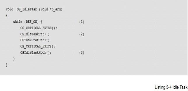
L5-4��1������������һ������ѭ���IJ���ȴ��κ��¼�������������Ϊ���ڴֵĴ������У���û���������ʱ����������Ȼ��ִ��ָ��� uC/OS-III ��û���������ߵľ������������ʱ��uC/OS-III �ͻ�� CPU �������������
L5-4(1) The idle task is a ��true��
infinite loop that never calls functions to ��wait for an event��. This is
because, on most processors, when there is ��nothing to do,�� the processor still
executes instructions. When ��C/OS-III determines that there is no other
higher-priority task to run, ��C/OS-III ��parks�� the CPU in the idle task.
Instead of having an empty ��for loop�� doing nothing, this ��idle�� time is used
to do something useful.
L5-4��2��������������ʱ���������������������
L5-4(2) Two counters are incremented
whenever the idle task runs.
OSIdleTaskCtr
���� 32 λ������������ģ��� uC/OS-III ��ʼ����ʱ������ֵ����λ�������ڱ�ʾ��������Ļ��������仰˵������õ������鿴�ñ������ͻῴ������ 0x00000000 �� 0xffffffff ֮�������OSIdleTaskCtr �������ٶ�ȡ���� CPU �Ŀ��������CPU Խ���У���ֵ����Խ�졣
OSIdleTaskCtr
is typically defined as a 32-bit unsigned integer (see OS.H). OSIdleTaskCtr is
reset once when ��C/OS-III is initialized. OSIdleTaskCtr is used to indicate
��activity�� in the idle task. In other words, if one monitors and displays
OSIdleTaskCtr, one should expect to see a value between 0x00000000 and
0xFFFFFFFF. The rate at which OSIdleTaskCtr increments depend on how busy the
CPU is at running the application code. The faster the increment, the less work
the CPU has to do in application tasks.
OSStatTaskCtr
Ҳ���� 32 λ������������ģ��ṩ������������� CPU �������ʡ�
OSStatTaskCtr
is also typically defined as a 32-bit unsigned integer (see OS.H) and is used
by the statistic task (described later) to get a sense of CPU utilization at
run time.
L5-4��3�����������ÿ��ѭ����������� OSIdleTaskHook()��������������ṩ���û���չӦ�á�����������в�Ҫ��д���ÿ���������Ĵ��룬���� uC/OS-III ��ֲ����˵����һ����ʶ��
L5-4(3)
Every time through the loop, OS_IdleTask() calls OSIdleTaskHook(), which is a
function that is declared in the ��C/OS-III port for the processor used.
OSIdleTaskHook() allows the implementer of the ��C/OS-III port to perform
additional processing during idle time. It is very important for this code to
not make calls that would cause the idle task to ��wait for an event��. This is
generally not a problem as most programmers developing ��C/OS-III ports know to
follow this simple rule.
OSIdleTaskHook()���Ա�дʹ CPU ���ڵ��ĵĴ��롣Ȼ���������Ļ�����ζ�� OSStatTaskCtr ���������ڲ��� CPU ��ʹ�����ˡ�
OSIdleTaskHook()
may be used to place the CPU in low-power mode for battery-powered applications
or to simply not waste energy as shown in the pseudo-code below. However, doing
this means that OSStatTaskCtr cannot be used to measure CPU utilization
(described later).
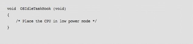
ͨ������£����жϷ���ʱ�������˳�����ģʽ��ISR �п��ܻ�����ijЩ�Ĵ����ָ� CPU �ٶ�Ϊȫ�ٻ�����Ҫ���ٶȡ�ISR ���Ի�����һ�������ȼ�����ÿ����������ȼ����ȿ�����������ȼ��ߣ���Ȼ��
ISR ���᷵�ص������������л�����������ȼ�����������������ɲ������߹���uC/OS-III �ͻ��л������������� OSIdleTaskHook()���������ģʽ��Ȼ����
OS_IdleTask() ��ѭ����
Typically,
most processors exit low-power mode when an interrupt occurs. Depending on the
processor, however, the Interrupt Service Routine (ISR) may have to write to
��special�� registers to return the CPU to its full or desired speed. If the ISR
wakes up a high-priority task (every task is higher in priority than the idle
task) then the ISR will not immediately return to the interrupted idle task,
but instead switch to the higher-priority task. When the higher-priority task
completes its work and waits for its event to occur, ��C/OS-III causes a context
switch to return to OSIdleTaskHook() just ��after�� the instruction that caused
the CPU to enter low-power mode. In turn, OSIdleTaskHook() returns
toOS_IdleTask() and causes another iteration through the ��for loop.��
5-6-2 ʱ������ OS-TickTask()
�������е�ʵʱϵͳ����Ҫ��һ�����ṩ������ʱ���ʱ��Դ������ʱ�����ڻ�ϵͳ���ڡ�uC/OS-III ��ʱ�����ڴ��������װ��OS_TICK.C �ļ��С�
OS_TickTask()���� uC/OS-III �����������ȼ����û������õġ�
Nearly
every RTOS requires a periodic time source called a Clock Tick or System Tick
to keep track of time delays and timeouts. ��C/OS-III��s clock tick handling is
encapsulated in the file OS_TICK.C.
��ͨ������ OS_CFG_APP.H �е� OS_CFG_TICK_TASK_PRIO����ͨ�����������ȼ��ϸߡ���ʵ�ϣ��������ȼ�Ӧ�����ñ���Ҫ��������ȼ��Ե͡�
OS_TickTask()
is a task created by ��C/OS-III and its priority is configurable by the user through
��C/OS-III��s configuration file OS_CFG_APP.H (see OS_CFG_TICK_TASK_PRIO).
Typically OS_TickTask() is set to a relatively high priority. In fact, the
priority of this task is set slightly lower than the most important tasks.
OS_TickTask()�����ٵȴ�������������ʱ������OS_TickTask()��һ���������������ȴ������� ISR ���ź���������½� 9"�жϹ���"����
OS_TickTask() is used by ��C/OS-III to keep track of tasks
waiting for time to expire or, for tasks that are pending on kernel objects
with a timeout. OS_TickTask() is a periodic task and it waits for signals from
the tick ISR (described in Chapter 9, ��Interrupt Management�� on page 157) as
shown in Figure 5-8.
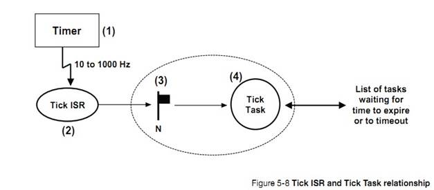
F5-8��1��ʹ��Ӳ����ʱ����������Ϊ�� 10 ��
1000Hz ֮���Ƶ�ʲ����жϣ�ͬʱҪ���� OS_CFG_APP.H �� OS_CFG_TICK_RATE ΪӲ����ʱ�����ж�Ƶ�ʡ�
F5-8(1) A hardware timer is generally used and configured
to generate an interrupt at a rate between 10 and 1000 Hz (see OS_CFG_TICK_RATE
in OS_CFG_APP.H). This timer is generally called the Tick Timer. The actual
rate to use depends on such factors as: processor speed, desired time
resolution, and amount of allowable overhead to handle the tick timer, etc.
ʱ���жϲ�����һ��Ҫ�� CPU ��������ʵ�ϣ������Դ������ľ��нϾ�ȷ��������ʱ��Դ�л�ã������Դ�ߣ�50-60Hz���ȡ�
The tick interrupt does not have to be generated by a timer
and, in fact, it can come from other regular time sources such as the
power-line frequency (50 or 60 Hz), which are known to be fairly accurate over
long periods of time.
F5-8��2���ٶ� CPU �ж�ʹ�ܣ�CPU ����ʱ���жϣ�����ռ��ǰ������ָ�� SP ָ��ʱ���жϷ������ʱ���жϷ������������OSTimeTick()����� OS_TIME.C��,Ȼ��ʱ�� ISR
������жϱ�־λ��Ȼ������ЩӦ���о���Ҫ�����жϱ�־�ٵ��� OSTimeTick()��������ʾ
F5-8(2) Assuming CPU interrupts are enabled, the CPU
accepts the tick interrupt, preempts the current task, and vectors to the tick
ISR. The tick ISR must call OSTimeTick() (see OS_TIME.C), which accomplishes
most of the work needed by ��C/OS-III. The tick ISR then clears the timer
interrupt (and possibly reloads the timer for the next interrupt). However,
some timers may need to be taken care of prior to calling OSTimeTick() instead
of after as shown below.
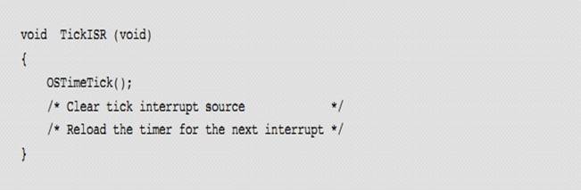
��
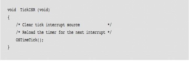
OSTimeTick()���ȵ��� OSTimeTickHook()�����ṩ���û���չ������ʱ��ʱ�ϲ���ʱ�û���Ҫ���Ĺ�����
OSTimeTick() calls OSTimeTickHook() at the very beginning
of
OSTimeTick() to give the opportunity to the ��C/OS-III port
developer to react as soon as possible upon servicing the tick interrupt.
F5-8��3��OSTimeTick()���ڱ��ʱ��������ʱ������ʱ���жϺ��������ܲ�������ִ�У���Ϊ�жϳ����ϵĿ�����һ����ʱ������������ȼ����������ʱ�� ISR ��uC/OS-III �᷵�ر���ϵ��������
F5-8(3) OSTimeTick()
calls a service provided by ��C/OS-III to signal the tick task and make that
task ready to run. The tick task executes as soon as it becomes the most
important task. The reason the tick task might not run immediately is that the
tick interrupt could have interrupted a task higher in priority than the tick
task and, upon completion of the tick ISR, ��C/OS-III will resume the
interrupted task.
F5-8��4����ʱ������ִ��ʱ������������������еȴ����������ȴ��¼���ʱ������������۵㣬����ᱻ����ʱ���б���ʱ����������ʱ���б��е���Щ��������ʱ������
F5-8(4) When
the tick task executes, it goes through a list of all tasks that are waiting
for time to expire or are waiting on a kernel object with a timeout. From this
point forward, this will be called the tick list. The tick task will make ready
to run all of the tasks in the tick list for which time or timeout has expired.
The process is explained below.
uC/OS-III
��ʱ����������ʱҲ�п��ܴ�����ϰٸ��������Ӧ����Ҫ�ܶ�����ʱ������ͨ��һ�ַ��������Щ�����Ƿ��������Ƿ���Ա�����Ϊ�������÷�������ռ��̫�� CPU ʱ�䡣��ͼ 5-9
��C/OS-III may need to place literally hundreds of tasks (if
an application has that many tasks) in the tick list. The tick list is
implemented in such a way that it does not take much CPU time to determine if
time has expired for those tasks placed in the tick list and, possibly makes
those tasks ready to run. The tick list is implemented as shown in Figure 5-9.
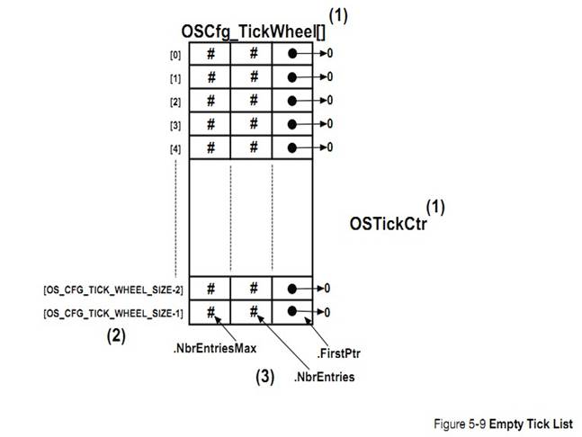
F5-9��1��ʱ���б��а�����һ������OSCfg_TickWheel[]����һ��������(OSTickCtr)��
F5-9(1) The
tick list consists of a table (OSCfg_TickWheel[]) and a counter (OSTickCtr).
F5-9��2���������� OS_CFG_TICK_WHEEL_SIZE ����¼�������ڱ���ʱ���õģ���� OS_CFG_APP.H������¼��ȡ���ڴ������� RAM ��Ӧ�����������������Ƽ�ֵΪ��������/4�����Ƽ�ʹ��ż������������ OS_CFG_TICK_WHEEL_SIZE Ϊ 10���� 11 ���棩����ʵ�ϣ�������һ���ܺõ�ѡ��
F5-9(2) The
table contains up to OS_CFG_TICK_WHEEL_SIZE entries, which is a compile time
configuration value (see OS_CFG_APP.H). The number of entries depends on the
amount of memory (RAM) available to the processor and the maximum number of
tasks in the application. A good starting point for OS_CFG_TICK_WHEEL_SIZE may
be: #Tasks / 4. It is recommended not to make OS_CFG_TICK_WHEEL_SIZE an even
multiple of the tick rate. If the tick rate is 1000 Hz and one has 50 tasks in
the application, avoid setting OS_CFG_TICK_WHEEL_SIZE to 10 or 20 (use 11 or 23
instead). Actually, prime numbers are good choices. Although it is not really
possible to plan at compile time what will happen at run time, ideally, the
number of tasks waiting in each entry of the table will be distributed
uniformly.
F5-9��3�����е�ÿ����¼���� 3 ��������.NbrEntriesMax��NbrEntries �� FirstPtr��
F5-9(3) Each entry in the table contains three
fields:.NbrEntriesMax, .NbrEntries and .FirstPtr.
NbrEntries
�������ӵ��ü�¼��������š�
.NbrEntries indicates the number of tasks linked to this
table entry.
NbrEntriesMax
�ٵ��������ȼ���ߵļ�¼�����ֵ�ڵ���OSStatReset()ʱ����λ��
.NbrEntriesMax
keeps track of the highest number of entries in the table. This value is reset
when the application code calls OSStatReset().
.FirstPtr
������һ��ָ��˫�������б���ָ�롣
.FirstPtr contains a pointer to a doubly linked list of
tasks (through the tasks OS_TCB) belonging to the list, at that table position.
��ʱ���ж�ÿ����һ�Σ�OSTickCtr ��ֵ�ͻᱻ OS_TickTask()����һ�Ρ�
The counter is incremented by OS_TickTask() each time the
task is signaled by the tick ISR.
������ OSTimeDly???()���� OS???Pend()ʱ���������ij�ʱʱ����� 0��������ᱻ�Զ��IJ���ʱ���б���
Tasks are automatically inserted in the tick list when the
application programmer calls a OSTimeDly??? () function, or when an OS???Pend()
call is made with a non-zero timeout value.
���� 5-1
��һ������������ʱ���б��в�������Ĺ��̣������ȼ���ʱ���б�Ϊ�գ�OS_CFG_TICK_WHEEL_SIZE ������Ϊ 12����ǰ�� OSTickCtr ֵΪ 10����ͼ 5-10���� OSTimeDly()������ʱ����Ӧ������ʱ���б������ٶ� OSTimeDly()�������±����ã�
Using an example to illustrate the process of inserting a
task in the tick list, let��s assume that the tick list is completely empty,
OS_CFG_TICK_WHEEL_SIZE is configured to 12, and the current value of OSTickCtr
is 10 as shown in Figure 5-10. A task is placed in the tick list when
OSTimeDly() is called and assume OSTimeDly() is called as follows:
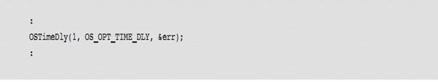
������ʾ��������Ҫ����ʱ 1 ��ʱ������Ϊ OSTickCtr ��ֵΪ 10�������ᴦ�ڵȴ�״ֱ̬�� OSTickCtr Ϊ 11��
Referring to the ��C/OS-III reference manual in Appendix A,
notice that this action indicates to ��C/OS-III to delay the current task for 1
tick. Since OSTickCtr has a value of 10, the task will be put to sleep until OSTickCtr
reaches 11 or at the very next clock tick interrupt.
���ᱻ���뵽OSCfg_TickWheel[]���������µĵ�ʽ��
Tasks are inserted in the OSCfg_TickWheel[] table using the
following equation:
MatchValue = OSTickCtr + dly
Index into OSCfg_TickWheel[] =MatchValue%OS_CFG_TICK_WHEEL_SIZE
"dly"�Ǵ��ݸ� OSTimeDly()�ĵ�һ�������������������Ϊ 1��
Where ��dly�� is the value passed in the first argument of
OSTimeDly() or, 1 in this example.
�������Ӽ���
We therefore obtain the following:
MatchValue = 11
Index into OSCfg_TickWheel[] = 11
��Ϊ�����ѭ���ģ���ģ������������һ��ʱ���֣�ÿһ����¼����ʱ���ֵ�һ���֡�
Because of the ��circular�� nature of the table (a modulo
operation using the size of the table), the table is referred to as a tick
wheel and each entry is a spoke in the wheel.
OSCfg_TickWheel[]������ 11 ָ������� TCB����һ�������TCB
��TickNextPtr ��ַ�����뵽����
OSCfg_TickWheel[11].FirstPtr���������� 11 �е��������ֵ������OSCfg_TickWheel[11].NbrEntries �ᱻ����Ϊ 1������Ҫע����ǣ� TCB �е�.TickSpokePtr �ᱻ���ӵ�&OSCfg_TickWheel[11]��
"MatchValue"�ᱻ���� TCB.TickCtrMatch �С���Ϊ���Dz��뵽��¼11 �ĵ�һ������.TickNextPtr ��.TickPrevPtr �ᱻ����Ϊָ�� NULL��
The OS_TCB of the task being delayed is entered at index 11
in OSCfg_TickWheel[] (i.e., spoke 11 using the wheel analogy). The OS_TCB of
the task is inserted in the first entry of the list (i.e., pointed to by
OSCfg_TickWheel[11].FirstPtr), and the number of entries at spoke 11 is
incremented (i.e.,OSCfg_TickWheel[11].NbrEntries will be 1). Notice that the
OS_TCB also links back to &OSCfg_TickWheel[11] and the ��MatchValue�� are
placed in the OS_TCB field .TickCtrMatch. Since this is the first task inserted
in the tick list at spoke 11, the .TickNextPtr and .TickPrevPtr both point to
NULL.

OSTimeDly()��Ҫ�չ�����һЩϸ�ڡ��ر�ģ��������پ߱����е��ʸ�ʱ��������ᱻ�� uC/OS-III �ľ����б����Ƴ����� uC/OS-III��Ҫ������һ������Ҫ�ľ�������ʱ���������ᱻ���á�����һ��ʱ������֮ǰ��������������� OSTimeDly()����
OSTimeDly() takes care of a few other details.
Specifically, the task is removed from ��C/OS-III��s ready list (described in
Chapter 6, ��The Ready List�� on page 123) since the task is no longer eligible
to run (because it is waiting for time to expire). Also, the scheduler is
called because ��C/OS-III will need to run the next most important ready-to-run
task.
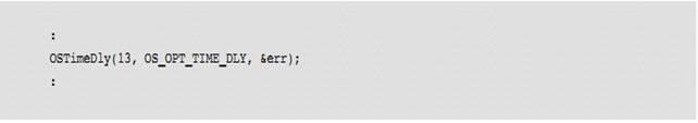
uC/OS-III
�������ƥ��ֵ��match value���ͼ�¼��
|
MatchValue
|
= 10+13
|
|
Index into
��
|
OSCfg_TickWheel[] = (10+13)%12
|
|
MatchValue
|
= 23
|
|
Index into
|
OSCfg_TickWheel[] = 11
|
�ڶ�������ᱻ���뵽ͬһ������ͼ 5-11 ��ʾ��������������¼����������ȷ���ȴ�ʱ�����ٵ�����λ�ڼ�¼ 11 ���е�ͷ����
The ��second task�� will be inserted at the same table entry
as shown in Figure 5-11. Tasks sharing the same spoke are sorted in ascending
order such that the task with the least amount of time remaining is placed at
the head of the list.
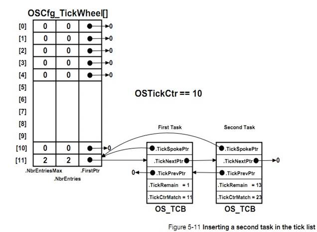
{����OS_TCB������TCB��һ���֣���ʵ��TCB����OS_TCB���Ͷ���ı���}
��ʱ������ִ��ʱ����� OS_TICK.C �е� OS_TickTask()��
OS_TickListUpdate()����������� OSTickCtr ��ֵ��ȷ��ʱ�����е���Щ��¼��Ҫ��ִ�С�Ȼ������������������¼�У���¼��.FirstPtr ��ΪNULL������¼�е�ÿ�� OS_TCB �ᱻ�����.TickCtrMatch ��ֵ�Ƿ��� OSTickCtr ��ֵ��ƥ�䡣���ƥ�䣬��������� OS_TCB �Ӽ�¼�б����Ƴ������������ֻ���ڵȴ������������ᱻ��������б��С���������ǵȴ�һ�������ҵȴ���ʱ�ˣ��������ᱻ�Ƴ�ʱ���б���Ҳ�ᱻ�Ƴ��ö���Ĺ�����С��������¼�еĶ��У�ֱ��TickCtrMatch ��ֵ�� OSTickCtr ��ֵ����ƥ��Ϊֹ��
When the tick task executes (see OS_TickTask() and also
OS_TickListUpdate() in OS_TICK.C), it starts incrementing OSTickCtr and
determines which table entry (i.e., which spoke) needs to be processed. Then,
if there are tasks in the list at this entry (i.e., .FirstPtr is not NULL),
each OS_TCB is examined to determine whether the .TickCtrMatch value ��matches��
OSTickCtr and, if so, we remove the OS_TCB from the list. If the task is only
waiting for time to expire, it will be placed in the ready list (described
later). If the task is pending on an object, not only will the task be removed from
the tick list, but it will also be removed from the list of tasks waiting on
that object. The search through the list terminates as soon as OSTickCtr does
not match the task��s .TickCtrMatch value; since there is no point in looking
any further in the list.
��Ҫע����ǣ�OS_TickTask()����ʱ�����в�����صĴֹ�������Ҫ���ٽ�ε���ʽ�����ġ�Ȼ������Ϊ��¼�����࣬�ٽ�ο��Ա���Ϊ�̡ܶ�
Note that OS_TickTask() does most of its work in a critical
section when the tick list is updated. However, because the list is sorted, the
critical section has a chance to be fairly short.
5-6-3 ͳ������ OS_StatTask()
��������ܹ�ͳ���ܵ� CPU ʹ����(0 �� 100%��,ÿ������� CPU ʹ���ʣ�0 �� 100%����ÿ������Ķ�ջʹ������
��C/OS-III contains an internal task that provides such
run-time statistics as overall CPU utilization (0 to 100%), per-task CPU
utilization (0-100%), and per-task stack usage.
ͳ�������� uC/OS-III ���ǿ�ѡ�ģ������� OS_CFG.H �е�OS_CFG_STAT_TASK_EN Ϊ 1 ʱ��ͳ������Ĵ���ᱻ�����ڳ����С�
The statistic task is optional in a ��C/OS-III application
and its presence is controlled by a compile-time configuration constant
OS_CFG_STAT_TASK_EN defined in OS_CFG.H.Specifically, the code is included in
the build when OS_CFG_STAT_TASK_EN is set to 1.
��Ȼ��ͳ����������ȼ������������ջ��С�� OS_CFG_APP.H �����á�
Also, the priority of this task and the location and size
of the statistic task��s stack is configurable via OS_CFG_APP.H
(OS_CFG_STAT_TASK_PRIO).
����� main()��ֻ������һ������ͨ������ AppTaskStat()����ʹ����ͳ������ʱ���ͱ����� AppTaskStat ���������ȵ���OSStatTaskCPUUsageInit()�����б� 5-5 ��ʾ���ڵ��� OSStart()֮ǰ���û�����������ֻ�ܴ���һ�������������������������
If the application uses the statistic task, it should call
OSStatTaskCPUUsageInit() from the first, and only the application task created
in the main() function as shown in Listing 5-5. The startup code should create
only one task before calling OSStart(). The single task created is, of course,
allowed to create other tasks, but only after calling OSStatTaskCPUUsageInit().
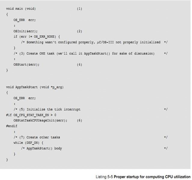
L5-5��1��CPU ���� main()������
L5-5(1) The
C compiler should start up the CPU and bring it to main() as is typical in most
C applications.
L5-5��2��main()��������
OSInit()��ʼ�� uC/OS-III���ٶ���OS_CFG_APP.H
������ OS_CFG_STAT_TASK_EN Ϊ 1��ʹ��ͳ������ͨ�� uC/OS-III ���صĴ�����ż��ϵͳ��ʼ���Ƿ�ɹ�������� OS.H �еĴ������ OS_ERR_???����
L5-5(2) main()
calls OSInit() to initialize ��C/OS-III. It is assumed that the statistics task
is enabled by setting OS_CFG_STAT_TASK_EN to 1 in OS_CFG_APP.H. Always examine
��C/OS-III��s returned error code to make sure the call was done properly. Refer
to OS.H for a list of possible errors, OS_ERR_???.
L5-5��3������һ������ AppTaskStart()����������������ʱ����һ���൱�ߵ����ȼ�����Ҫ�����ȼ� 0����Ϊ����Ϊ uC/OS-III �����ģ���
uC/OS-III
�����û��ڵ��� OSStart()֮ǰ�������������Ȼ�������õ�ͳ������ͳ�� CPU ��ʹ����ʱ������ OSStart()֮ǰֻ�ܴ���һ������
L5-5(3) As
the comment indicates, creates a single task called AppTaskStart() in the
example (its name is left to the creator��s discretion). When creating this
task, give it a fairly high priority (do not use priority 0 since it��s reserved
for ��C/OS-III).
Normally, ��C/OS-III allows the user to create as many tasks
as are necessary prior to calling OSStart(). However, when the statistic task
is used to compute overall CPU utilization, it is necessary to create only one
task.
L5-5��4������ OSStart()����
uC/OS-III ��ʼ�������ȼ���ߵ����������ӣ���������� AppTaskStart()�������ʱ���Ѿ�������������ˣ�OS_IdleTask()��OS_TickTask()��OS_StatTask()��OS_TaskTmr()��AppTaskStart()��
L5-5(4) Call
OSStart() to let ��C/OS-III start the highest-priority task which, should be
AppTaskStart(). At this point, there should be either four or five tasks
created (the timer task is optional): ��C/OS-III creates up to four tasks
(OS_IdleTask(), OS_TickTask(), OS_StatTask() and OS_TaskTmr()), and now
AppTaskStart().
L5-5��5���������Ӧ�������úͿ���ʱ���жϣ���ʼ������ʱ��ʱ�ӵ�Ӳ����ʱ�����������жϵ����ʡ�������ʱ���� OS_CFG_APP.H �е�OS_CFG_STAT_TASK_RATE�������⣬Micrium �ṩ�����ӹ����а����˻����İ弶֧�ְ� BSP��BSP ��ʼ���� CPU �ܶ���Ҳ���� uC/OS-III ��Ҫ������ʱ��Դ�������Ҫ���û������ڿ��������е���
BSP_Init()��ʼ�� BSP ����
L5-5(5) The
start task should then configure and enable tick interrupts. This most likely
requires that the user initialize the hardware timer used for the clock tick
and have it interrupt at the rate specified by OS_CFG_STAT_TASK_RATE (see
OS_CFG_APP.H). Additionally, Micri��m provides sample projects that include a
basic board-support package (BSP). The BSP initializes many aspects of the CPU
as well as the periodic time source required by ��C/OS-III. If available, the
user may utilize BSP services by calling BSP_Init() from the startup task.
After this point, no further time source initialization is required by the
user.
L5-5��6������ OSStatTaskCPUUsageInit()����û������Ӧ����������ʱ������ 1/OS_CFG_STAT_TASK_RATE ��� OSStatTaskCtr �ļ���ֵ����OSStatTaskCtr �����ֵ������ζ�� CPU �Ŀ���ʱ�Ĺ������ʡ����磬���ϵͳ�в�����Ӧ������OSStatTaskCtr �� 0 ��ʼ������10,000,000 ����
1/OS_CFG_STAT_TASK_RATE
�롣������Ӧ������� OSStatTaskCtr ÿ
1/OS_CFG_STAT_TASK_RATE ����һ�Ρ��õ���ֵ����ﵽ 10,000,000��CPU �����������¼��㣺
L5-5(6) Call
OSStatTaskCPUUsageInit(). This function determines the maximum value that
OSStatTaskCtr (see OS_IdleTask()) can count up to for 1/OS_CFG_STAT_TASK_RATE
second when there are no other tasks running in the system (apart for the other
��C/OS-III tasks). For example, if the system does not contain an application
task and OSStatTaskCtr counts from 0 to 10,000,000 for 1/OS_CFG_STAT_TASK_RATE
second, when adding tasks, and the
test is redone every 1/OS_CFG_STAT_TASK_RATE second, the
OSStatTaskCtr will not reach 10,000,000 and actual CPU utilization is
determined as follows:

������²�õ� OSStatTaskCtr ֵΪ 7,500,000����ô CPU ��������Ϊ 25%��
For example, if when redoing the test, OSStatTaskCtr
reaches 7,500,000 the CPU is busy 25% of its time running application tasks:

L5-5��7��Ȼ���� AppTaskStart()����������Ӧ������
AppTaskStart() can then create other application tasks as needed.
������ǰ�����ģ�uC/OS-III ������� CPU ʹ���ʴ�������� TCB��
As previously described, ��C/OS-III stores run-time
statistics for a task in each task��s OS_TCB.
OS_StatTask()Ҳ���Լ���ÿ�������ջ��ʹ������ͨ������OSTaskStkChk()������������������ÿ������ OS_TCB��StkFree�� StkUsed �С�
OS_StatTask() also computes stack usage of all created tasks
by calling OSTaskStkChk() and stores the return values of this function (free
and used stack space) in the .StkFree and .StkUsed field of the task��s OS_TCB,
respectively.
5-6-4 ��ʱ������ OS_TmrTask()
{�����˵�Ķ�ʱ������������ʱ��} uC/OS-III Ϊ�û��ṩ�˶�ʱ��������Ӧ������ OS_TMR.C �С�
��C/OS-III provides timer services to the application
programmer. Code to handle timers is found in OS_TMR.C.
��ʱ�������ǿ�ѡ�ģ�ͨ���� OS_CFG.H �е� OS_CFG_TMR_EN����Ϊ 1 ʹ�ܡ�������Ϊ 1 ʱ�����Ĵ���Żᱻ���ӵ����մ����С�
The timer task is optional in a ��C/OS-III application and
its presence is controlled by the compile-time configuration constant
OS_CFG_TMR_EN defined in OS_CFG.H. Specifically, the code is included in the
build when OS_CFG_TMR_EN is set to 1.
����ʱ������ݼ����������� 0 ʱ�������оͻ���ûص��������ص�������һ�������������û����塣��ˣ��ص�������������������ر� LED�����������������һЩ�������û����Դ����������ʱ����ֻ�����ڴ������� RAM������ʱ�������� 12 ����ϸ���ܡ�
Timers are countdown counters that perform an action when
the counter reaches zero. The action is provided by the user through a callback
function. A callback function is a function that the user declares and that
will be called when the timer expires. The callback can thus be used to turn on
or off a light, a motor, or perform whatever action needed. It is important to
note that the callback function is called from the context of the timer task.
The application programmer may create an unlimited number of timers (limited
only by the amount of available RAM). Timer management is fully described in
Chapter 12, ��Timer Management�� on page 193 and the timer services available to
the application programmer are described in Appendix A, ����C/OS-III API
Reference Manual�� on page 375.
OS_TmrTask()��һ���� uC/OS-III ���������ٶ�����OS_CFG.H �е� OS_CFG_TMR_EN Ϊ 1������ͨ�� OS_CFG_APP.H �е� OS_CFG_TMR_TASK_PRIO �������ȼ���һ������£��������ȼ�����Ϊ�еȡ�
OS_TmrTask() is a task created by ��C/OS-III (this assumes
setting OS_CFG_TMR_EN to 1 in OS_CFG.H) and its priority is configurable by the
user through ��C/OS-III��s configuration file OS_CFG_APP.H (see
OS_CFG_TMR_TASK_PRIO). OS_TmrTask() is typically set to a medium priority.
OS_TmrTask()�����ں������ж�Դ����ʱ����Ȼ������ʱ��ͨ����Ҫ�ϵ͵��ʣ�����Ϊ 10Hz��������ͨ��������ʱ����Ƶ�����仰˵�����ʱ������Ϊ 1000Hz,������Ҫ�Ķ�ʱ������Ϊ 10Hz,��ʱ�������ÿ 100 ��ʱ�������һ�Ρ���ͼ 5-12
OS_TmrTask() is a periodic task using the same interrupt
source that was used to generate clock ticks. However, timers are generally
updated at a slower rate (i.e., typically 10 Hz) and the timer tick rate is
divided down in software. In other words, if the tick rate is 1000 Hz and the
desired timer rate is 10 Hz, the timer task will be signaled every 100th tick
interrupt as shown in Figure 5-12.
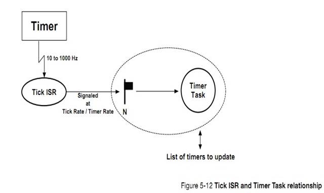
5-6-5 �жϴ������� OS_IntQTask()
������ OS_CFG.H �е� OS_CFG_ISR_POST_DEFERRED_EN Ϊ1 ʱ��uC/OS-III �ͻᴴ��һ���������������Ǿ������ ISR �ж� post �����ĵ��ã����ź�������Ϣ�ȶ����ȴ���ý���У��˳��жϺ����жϴ���������ɽ���Щ�����ύ������
When setting the compile-time configuration constant
OS_CFG_ISR_POST_DEFERRED_EN in OS_CFG.H to 1, ��C/OS-III creates a task (called
OS_IntQTask()) responsible for ��deferring�� the action of OS service post calls
from ISRs.
����� 4 �¡��ٽ�Ρ������ܵģ�uC/OS-III ͨ������/�ر��жϡ���/���������������ٽ�Ρ����ѡ���һ�ַ�����ISR ���õ� post ����������ֱ�ӷ��ʾ����б���������еȡ�
As described in Chapter 4, ��Critical Sections�� on page 69,
��C/OS-III manages critical sections either by disabling/enabling interrupts, or
by locking/unlocking the scheduler. If selecting the latter method (i.e.,
setting OS_CFG_ISR_POST_DEFERRED_EN to 1), ��C/OS-III ��post�� functions called
from interrupts are not allowed to manipulate such internal data structures as
the ready list, pend lists, and others.
�� ISR ���� uC/OS-III �ṩ�� post ����ʱ��ISR Ҫ�ύ�����ݻᱻ���ƣ������ݵ�Ŀ�ĵػᱻ�ŵ�һ������Ķ��С�"holding"���С������е�Ƕ���жϽ���ʱ��uC/OS-III �л����жϴ����������Ὣ������"holding"�����е���Ϣ�����ύ���ʵ�������������ⲽ���Ŀ���Ǽ�С���ж�ʱ�䡣
When an ISR calls one of the ��post�� functions provided by
��C/OS-III, a copy of the data posted and the desired destination is placed in a
special ��holding�� queue. When all nested ISRs complete, ��C/OS-III context
switches to the ISR handler task (OS_IntQTask()), which ��re-posts�� the
information placed in the holding queue to the appropriate task(s). This extra
step is performed to reduce the amount of interrupt disable time that would
otherwise be necessary to remove tasks from wait lists, insert them in the
ready list, and perform other time-consuming operations.
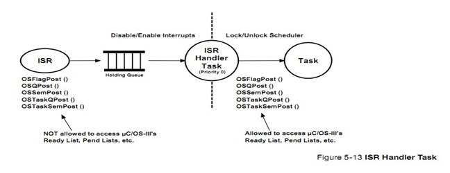
OS_IntQTak()�� uC/OS-III �������������ȼ�ͨ������Ϊ 0��������ȼ�������� OS_CFG_ISR_POST_DEFERRED_EN ������Ϊ 1��ʹ�������������������������ȼ��Ͳ�������Ϊ 0��
OS_IntQTask() is created by ��C/OS-III and always runs at
priority 0 (i.e., the highest priority). If OS_CFG_ISR_POST_DEFERRED_EN is set
to 1, no other task will be allowed to use priority 0.
������һ�μij����ڵ� CPU ϵͳ�У��κ�ʱ��ֻ����һ������ CPU ���С�uC/OS-III ֧�ֶ�����������û�����ƣ��������� CPU �Ĵ洢�ռ䣬��������ռ�����ݿռ䣩��
A task is a simple program that thinks it has the CPU all
to itself. On a single CPU, only one task executes at any given time. ��C/OS-III
supports multitasking and allows the application to have any number of tasks.
The maximum number of tasks is actually only limited by the amount of memory
(both code and data space) available to the processor.
A task can be implemented as a run-to-completion task in
which the task deletes itself when it is finished or more typically as an
infinite loop, waiting for events to occur and processing those events.
A task needs to be created. When creating a task, it is
necessary to specify the address of an OS_TCB to be used by the task, the
priority of the task, and an area in RAM for the task��s stack. A task can also
perform computations (CPU bound task), or manage one or more I/O (Input/Output)
devices.
uC/OS-III
��������ڲ�����������ʱ�������жϴ�������ͳ������ʱ������������ʱ�������DZ���ģ�ͳ������ʱ�������жϴ��������ǿ�ѡ��ġ�
��C/OS-III creates up to five internal tasks: the idle task,
tick task, ISR handler task, statistics task, and timer task. The idle and tick
tasks are always created while statistics and timer tasks are optional.
6�������б�
�����е��������ھ����б��С������б����� 2 �����֣�λӳ������������ȼ���Ϣ��һ��������������ָ����������ָ�롣
Tasks that are ready to execute are placed in the Ready
List. The ready list consists of two parts: a bitmap containing the priority
levels that are ready and a table containing pointers to all the tasks ready.
ͼ 6-1 �� 6-3 ��ʾ�����ȼ���λӳ���顣���Ŀ���ȡ����CPU_DATA ���������ͣ��� CPU.H������������ 8 λ��16 λ��32 λ�����ݴ�������Ӧ���趨��
Figures 5-1 to 5-3 show the bitmap of priorities that are
ready. The ��width�� of the table depends on the data type CPU_DATA (see CPU.H),
which can either be 8-, 16- or 32-bits. The width depends on the processor
used.
uC/OS-III
֧�ֶ�� OS_CFG_PRIO_MAX �ֲ�ͬ�����ȼ�����OS_CFG.H������ uC/OS-III �У���ֵԽС���ȼ�Խ�ߡ�������ȼ� 0 �����ȼ���ߵġ����ȼ� OS_CFG_PRIO_MAX-1 �����ȼ���͡�
��C/OS-III allows up to OS_CFG_PRIO_MAX different priority
levels (see OS_CFG.H). In ��C/OS-III, a low-priority number corresponds to a
high-priority level. Priority level zero (0) is thus the highest priority
level. Priority OS_CFG_PRIO_MAX-1 is the lowest priority level.
uC/OS-III
��������ȼ�Ψһ�ط������������������������������Ϊ������ȼ������������������ˣ�������������ȼ���λӳ�������Ӧλ�ͻᱻ����Ϊ 1��
��C/OS-III uniquely assigns the lowest priority to the idle
task. No other tasks are allowed at this priority level. If there are tasks
that are ready-to-run at a given a priority level, then its corresponding bit
is set (i.e., 1) in the bitmap table. Notice in Figures 5-1 to 5-3 that
��priority levels�� are numbered from left to right and, the priority level
increases (moves toward lower priority) with an increase in table index. The
order was chosen to be able to use a special instruction called Count Leading
Zeros (CLZ), which is found on many modern processors.
���������֧��λ����ָ�� CLZ�����ָ���ӿ�λӳ��������ù��̡�
This instruction greatly accelerates the process of
determining the highest priority level.
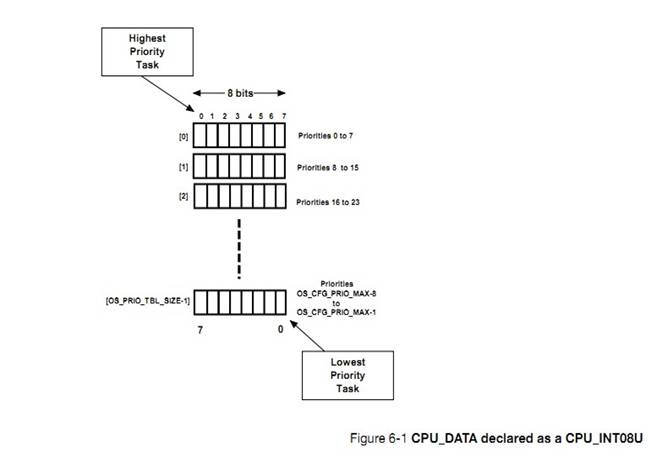
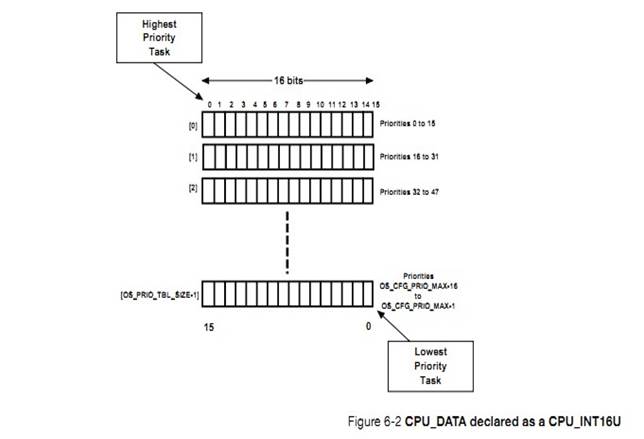
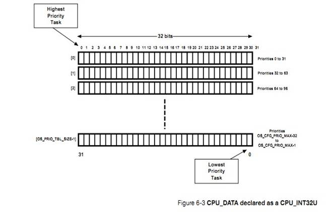
OS_PRIO.C
�а�����λӳ��������á���������ҵ���ش��롣��Щ�������� uC/OS-III ���ڲ������������û�������Ż���
OS_PRIO.C contains the code to set, clear, and search the
bitmap table. These functions are internal to ��C/OS-III and are placed in
OS_PRIO.C to allow them to be optimized in assembly language by replacing
OS_PRIO.C with an assembly language equivalent OS_PRIO.ASM, when necessary.
|
����
|
����
|
|
OS_PrioGetHighest()
|
����������ȼ�
Find the highest
priority level
|
|
OS_PrioInsert()
|
����λӳ�������Ӧ��λ
Set bit corresponding to priority level in the bitmap
table
|
|
OS_PrioInsert()
|
���λӳ�������Ӧ��λ
Clear bit corresponding to priority level in the bitmap
table
|
�� 6-1 ���ȼ���صĺ���
Ϊ��ȷ�������б������ȼ���ߵ�����λӳ����ᱻɨ�裬ͨ��OS_PrioGetHighest()�����ҵ����ȼ���ߵ����������б� 6-1 ��ʾ
To
determine the highest priority level that contains ready-to-run tasks, the
bitmap table is scanned until the first bit set in the lowest bit position is
found using OS_PrioGetHighest().The code for this function is shown in Listing
6-1.
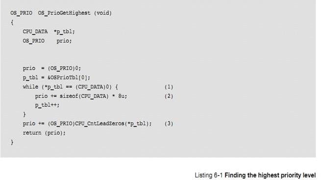
L6-1��1��OS_PrioGetHighest()����ɨ�� OSPrioTbl[]��ֱ���ҵ��� 0 �ļ�¼�����ѭ�����ջ�ֹͣ����Ϊ�����з� 0 ��¼����������Ĵ���)��
L6-1(1)
OS_PrioGetHighest() scans the table from OSPrioTbl[] until a non-zero entry is
found. The loop will always terminate because there will always be a non-zero
entry in the table because of the idle task.
L6-1��2�� ���������ȫ�� 0 ��¼ʱ���ͻ����һ�����в��ҡ����ȼ�"prio"�ᱻ���ӣ�������� 32 λ���ͽ� prio ���� 32����
L6-1(2) Each time a zero entry is
found, we move to the next table entry and increment ��prio�� by the width (in
number of bits) of each entry. If each entry is 32-bits wide, ��prio�� is incremented
by 32.
L6-1��3�����ҵ���һ���� 0 λʱ�������λ֮ǰ 0 λ�ĸ��������ظ����ȼ�ֵ����� CPU �ṩ����ָ�����ͨ�����ָ���Ż����롣��� CPU û�����ָ���ô���ָ���ֻ���� C ����ģ���ˡ�
L6-1(3) Once the first non-zero entry
is found, the number of ��leading zeros�� of that entry is simply added and
return the priority level back to the caller. Counting the number of zeros is a
CPU-specific function so that if a particular CPU has a built-in CLZ
instruction, it is up to the implementer of the CPU port to take advantage of
this feature. If the CPU used does not provide that instruction, the
functionality must be implemented in C.
���� CPU_CntLeadZeros()ͳ���� CPU_DATA ��¼�� 0 �ĸ���������߿�ʼ����λ�ƣ������磬�ٶ�λӳ����� 32 λ��0xF0001234 ���صķ� 0 λǰ
0 λ���ĸ����� 0��0x00F01234 ���ص��� 8��
The
function CPU_CntLeadZeros() simply counts how many zeros there are in a CPU_DATA
entry starting from the left (i.e., most significant bit). For example,
assuming 32 bits, 0xF0001234 results in 0 leading zeros and 0x00F01234 results
in 8 leading zeros.
�Զ��������Ե�ɨ���������Ч�ʵ��µġ�Ȼ����������ȼ����ٵĻ���ɨ���Ƿdz���ġ���ʵ�ϣ���һЩ���������Ż�ɨ�衣���磬���ʹ�� 32 λ��������Ӧ������Ҫ�����ȼ������� 64����ô��������Ϳ��Ա��Ż����б� 6-2 ��ʾ����������������ָ��ò��ִ������ͨ����౻�Ż�Ϊ�̵ܶĴ��롣
At
first view, the linear path through the table might seem inefficient. However,
if the number of priority levels is kept low, the search is quite fast. In
fact, there are several optimizations to streamline the search. For example, if
using a 32-bit processor and you are satisfied with limiting the number of
different priority levels to 64, the above code can be optimized as shown in
Listing 6-2. In fact, some processors have built-in ��Count Leading Zeros��
instructions and thus, the code can be written with just a few lines of
assembly language. Remember that with ��C/OS-III, 64 priority levels does not
mean that the user is limited to 64 tasks since with ��C/OS-III, any number of
tasks are possible at a given priority level.
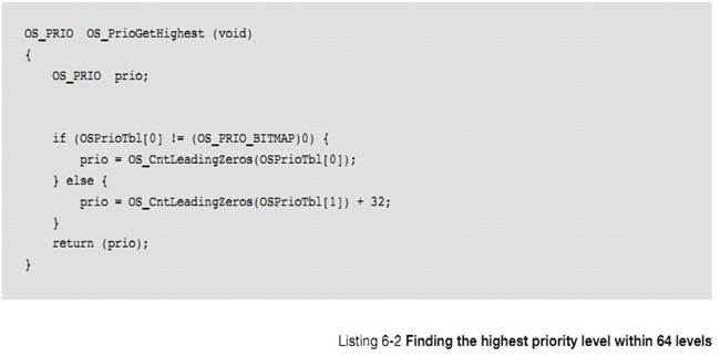
�������е����ŵ������б��У���ͼ 6-1�������б���һ�����飨OSRdyList[]������һ���� OS_CFG_PRIO_MAX ����¼����¼����������ΪOS_RDY_LIST(�� OS.H)�������б��е�ÿ����¼���������������� .Entries ��.TailPtr ��.HeadPtr��
Tasks
that are ready to run are placed in the Ready List. As shown in Figure 6-1, the
ready list is an array (OSRdyList[]) containing OS_CFG_PRIO_MAX entries, with
each entry defined by the data type OS_RDY_LIST (see OS.H). An OS_RDY_LIST
entry consists of three fields: .Entries, .TailPtr and .HeadPtr.
.Entries
�и����ȼ��ľ������������������ȼ���û���������ʱ��.Entries �ͻᱻ����Ϊ 0��
.Entries
contains the number of ready-to-run tasks at the priority level corresponding
to the entry in the ready list. .Entries is set to zero (0) if there are no
tasks ready to run at a given priority level.
.TailPtr
��.HeadPtr ���ڸ����ȼ���������Ľ���˫���б���.HeadPtr
ָ���б���ͷ����.TailPtr ָ���б���β����
.TailPtr
and .HeadPtr are used to create a doubly linked list of all the tasks that are
ready at a specific priority. .HeadPtr points to the head of the list and
.TailPtr points to its tail.
���еļ�¼����������ȼ��йء����磬���һ����������ȼ��� 5����ô��������ʱ�ᱻ���� OSRdyList[5]�С�
The
��index�� into the array is the priority level associated with a task. For
example, if a task is created at priority level 5 then it will be inserted in
the table at OSRdyList[5] if that task is ready to run.
�� 6-2 ���г���������б���صIJ�����������Щ���� uC/OS-III ���ڲ��������û����ܵ������ǡ�
Table
6-2 shows the functions that ��C/OS-III uses to manipulate entries in the ready
list.These functions are internal to ��C/OS-III and the application code must
never call them.
|
������
|
����
|
|
OS_RdyListInit()
|
��ʼ�������б�Ϊ��
Initialize the ready list to ��empty�� (see Figure 6-4)
|
|
OS_RdyListInsert()
|
����һ�� TCB �������б�
Insert a TCB into the ready list
|
|
OS_RdyListInsertHead()
|
����һ�� TCB �������б���ͷ��
Insert a TCB at the head of the list
|
|
OS_RdyListInsertTail()
|
����һ�� TCB �������б���β��
Insert a TCB at the tail of the list
|
|
OS_RdyListMoveHeadToTail()
|
�� TCB ���б���ͷ���Ƶ�β��
Move a TCB from the head to the tail of the list
|
|
OS_RdyListRemove()
|
�� TCB �Ӿ����б����Ƴ�
Remove a TCB from the ready list
|
�� 6-2 ������б���صĺ���
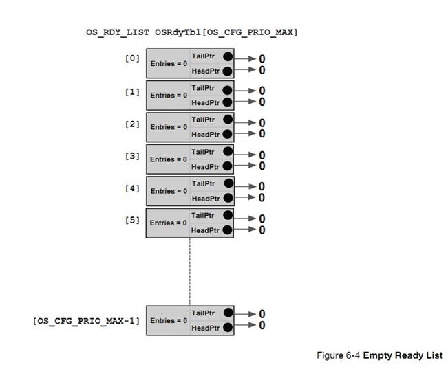
F6-4��1����ͼ��ʾ���Ǿ����б�Ϊ��ʱ��״̬��
F6-4(1) There is only one entry in
OSRdyList[OS_CFG_PRIO_MAX-1], the idle task.
F6-4��2���ж��������ȼ��������б��о��ɶ�������¼��ÿ����¼�ж��� 3 ��������Entries Ϊ�ü�¼�е���������.PrevPtr ��.NextPtr ����ָ�������ͬ���ȼ��� TCB ��ɵ�˫���б������ڿ�������������ֵΪ NULL��
F6-4(2) The list points to OS_TCBs.
Only relevant fields of the TCB are shown. The .PrevPtr and .NextPtr are used
to form a doubly linked list of OS_TCBs associated to tasks at the same
priority. For the idle task, these fields always point to NULL.
F6-4��3�����ȼ� 0 ��Ϊ�жϴ����������ģ������� OS_CFG.H �е�OS_CFG_ISR_DEFERRED_EN Ϊ 1��������������£�����Ψһһ���ܱ���Ϊ���ȼ� 0 ������
F6-4(3) Priority 0 is reserved to the
ISR handler task when OS_CFG_ISR_DEFERRED_EN is set to 1 in OS_CFG.H. In this
case, this is the only task that can run at priority 0.
�ٶ� uC/OS-III �ڲ�������ʹ�ܡ�ͼ 6-5 ��ʾ�˵� OSInit()�����ú�ľ����б���
Assuming
all internal ��C/OS-III��s tasks are enabled, Figure 6-5 shows the state of the
ready list after calling OSInit() (i.e., ��C/OS-III��s initialization). It is
assumed that each ��C/OS-III task had a unique priority. With ��C/OS-III, this
does not have to be the case.
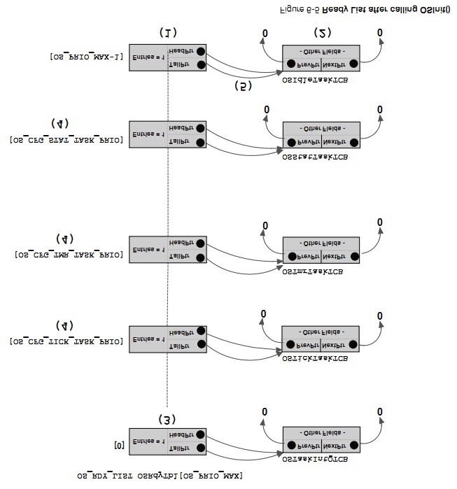
F6-5��1����ͼ��ʾ��ʱ������������������������Լ������ȼ��� uC/OS-III ���������������ͬ�����ȼ����ر�ģ�ʱ����������ȼ�Ҫ���ڶ�ʱ������ʱ����������ȼ���Ҫ��ͳ������
F6-5(1) The tick task and the other
two optional tasks have their own priority level, as shown. ��C/OS-III enables
the user to have multiple tasks at the same priority and thus, the tasks could
be set up as shown. Typically, one would set the priority of the tick task
higher than the timer task and, the timer task higher in priority than the
statistic task.
F6-5��2����ij�����ȼ���ֻ��һ�������ʱ������ͷָ���βָ���ָ��ͬһ�� TCB��
F6-5(2) Both the tail and head
pointers point to the same TCB when there is only one TCB at a given priority
level.
uC/OS-III
�ṩ�ܶ��������������ӵ������б��С������Եķ����� OSTaskCreate()����ͨ�����������е����������������б��С���ͼ 6-6 ��ʾ�������б��и����ȼ����Ѿ������������ˡ�OSTaskCreate()�ͻὫ���������뵽�б���δ����
Tasks
are added to the ready list by a number of ��C/OS-III services. The most obvious
service is OSTaskCreate(), which always creates a task in the ready-to-run
state and adds the task to the ready list. As shown in Figure 6-6, when
creating a task, and specifying a priority level where tasks already exist (two
in this example) in the ready list at that priority level, OSTaskCreate() will
insert the new task at the end of the list of tasks at that priority level.
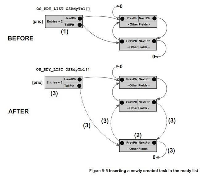
F6-6��1���ڵ��� OSTaskCreate()֮ǰ���Ѿ������������ھ����б��еĸ����ȼ����ˡ�
F6-6(1) Before calling OSTaskCreate()
(in this example), two tasks were in the ready list at priority ��prio��.
F6-6��2��һ���µ� TCB ���ݸ�
OSTaskCreate()��Ȼ�� uC/OS-III ��ʼ����� TCB��
F6-6(2) A new TCB is passed to
OSTaskCreate() and, ��C/OS-III initialized the contents of that TCB.
F6-6��3��OSTaskCreate()����
OS_RdyListInsertTail()��OS_RdyListInsertTail()�������ǽ������ӽ����� TCB ���ӵ����������ж�Ӧ���ȼ���¼���������ĸ�ָ�룬�����б���������������������������¼�е�.Entries ��ֵ��һ����OSTaskCreate()������� OS_PrioInsert()����λӳ����е���Ӧλ��Ȼ��������
OS_PrioInsert()�Ƿdz���ģ�������Ӱ�쵽Ӧ�õ����ܡ�
F6-6(3)
OSTaskCreate() calls OS_RdyListInsertTail(), which links the new TCB to the
ready list by setting up four pointers and also incrementing the .Entries field
of OSRdyList[prio]. Not shown in Figure 6-6 is that OSTaskCreate() also calls
OS_PrioInsert() to set the bit in the bitmap table. Of course, this operation
is not necessary as there are already entries in the list at this priority.
However, OS_PrioInsert() is a very fast call and thus it should not affect
performance.
��һ��������һ��������ͬ���ȼ����������������ᱻ���ӵ������ȼ����е�β������Ϊ������ͬ���ȼ�����£�û�������������������У���Ȼ������һ��������һ�����в�ͬ���ȼ�������ʱ������µ�����ͻ�ŵ���Ӧ���ȼ��б��е��ײ���
The
reason the new TCB is added to the end of the list is that the current head of
the list could be the task creator and, at the same priority, there is no
reason to make the new task the next task to run. In fact, a task being made
ready will be inserted at the tail of the list if the current task is at the
same priority. However, if a task is being made ready at a different priority
than the current task, it will be inserted at the head of the list.
uC/OS-III
֧���������������ȼ���Ȼ�����������ϵͳ�����������ᳬ�� 64 �֡�
��C/OS-III
supports any number of different priority levels. However, 256 different
priority levels should be sufficient for the most complex applications and most
systems will not require more than 64 levels.
�������а����������ݽṹ��λӳ����������ĸ����ȼ�������������У����ȼ��б��а�����������ȼ��µȴ����е�����
The
ready list consist of two data structures: a bitmap table that keeps track of
which priority level is ready, and a table containing a list of all the tasks
ready at each priority level.
������֧������ָ�� CLZ ��ӿ�λӳ�����ɨ���ٶȡ�{ע�⣺�������е�����Ҳ�����ھ����б��С�}
Processors
having ��count leading zeros�� instructions can accelerate the table lookup
process used in determining the highest priority task.
7������
�����������������������˳��uC/OS-III ��һ������ռ�ģ��������ȼ����ںˡ���������Ҫ��ÿ������������һ�����ȼ���uC/OS-III ֧�ֶ������ӵ����ͬ�����ȼ���
The
scheduler, also called the dispatcher, is a part of ��C/OS-III responsible for
determining which task runs next. ��C/OS-III is a preemptive, priority-based
kernel. Each task is assigned a priority based on its importance. The priority
for each task depends on the application, and ��C/OS-III supports multiple tasks
at the same priority level.
������ռ�ġ���ζ���¼�����ʱ������¼��ø����ȼ���������uC/OS-III ���Ͻ� CPU �Ŀ���Ȩ���������ȼ�������ˣ���һ�������ύ�ź�����������Ϣ��һ�������ȼ������������������ˣ�����ǰ������ͻᱻֹͣ���������ȼ��������� CPU �Ŀ���Ȩ�����Ƶģ��� ISR �ύ�ź���������Ϣ��һ�������ȼ������������������ˣ�����ô�жϷ��ص�ʱ�᷵�ص�ԭ�����Ǹ����ȼ�����
The
word preemptive means that when an event occurs, and that event makes a more
important task ready to run, then ��C/OS-III will immediately give control of
the CPU to that task. Thus, when a task signals or sends a message to a
higher-priority task, the current task is suspended and the higher-priority
task is given control of the CPU. Similarly, if an Interrupt Service Routine
(ISR) signals or sends a message to a higher priority task, when the message is
completed, the interrupted task remains suspended, and the new higher priority
task resumes.
uC/OS-III
ͨ�����ַ��������ж��ύ���¼�:ֱ���ύ���ӳ��ύ����Щ�����½� 9 ����ϸ���ܡ��ӵ��ȵĽǶȿ��������ַ��������Ľ����һ���ģ�������ȼ��ľ��������ռ�� CPU ��ͼ 6-1 �� 6-2 ��ʾ��
��C/OS-III
handles event posting from interrupts using two different methods: Direct and
Deferred Post. These will be discussed in greater detail in Chapter 9,
��Interrupt Management�� on page 157. From a scheduling point of view, the end
result of the two methods is the same; the highest priority and ready task will
receive the CPU as shown in Figures 6-1 and 6-2.
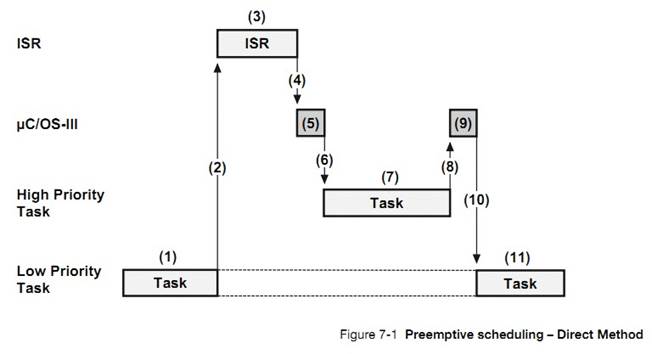
F7-1��1��һ�������ȼ���������ִ�У���ʱ�жϷ����ˡ�
F7-1(1) A low priority task is
executing, and an interrupt occurs.
F7-1��2������ж�ʹ�ܣ�ָ��ָ�� IP ����ת���жϷ������
F7-1(2) If interrupts are enabled,
the CPU vectors (i.e., jumps) to the ISR that is responsible for servicing the
interrupting device.
F7-1��3���жϷ����������صij������ź�������Ϣ��һ�������ȼ��������ȼ���������
F7-1(3) The ISR services the device
and signals or sends a message to a higher-priority task waiting to service
this device. This task is thus ready to run.
F7-1��4���жϷ��������ɲ��������� CPU �Ŀ���Ȩ���� uC/OS-III��
F7-1��4��When
the ISR completes its work it makes a service call to ��C/OS-III.
F7-1��5��uC/OS-III ִ����Ӧ�IJ�����
F7-1��6����Ϊ������������һ������Ҫ������uC/OS-III �����᷵���ж�ǰ�Ǹ������ȼ���������ִ�и����ȼ�����
F7-1(6) Since there is a more
important ready-to-run task, ��C/OS-III decides to not return to the interrupted
task but switches to the more important task. See Chapter 8, ��Context
Switching�� on page 147 for details on how this works.
F7-1��7����ʼִ�и����ȼ�����
F7-1��8�������ȼ���������ɺ� CPU �Ŀ���Ȩ���� uC/OS-III��
F7-1��8��The
higher priority task services the interrupting device and, when finished, calls
��C/OS-III asking it to wait for another interrupt from the device.
F7-1��9��uC/OS-III ִ����Ӧ�IJ�����
F7-1��10��uC/OS-III ת��ִ��ԭ���Ǹ������ȼ�����
F7-1(10) ��C/OS-III blocks the high-priority task
until the next device interrupts. Since the device has not interrupted a second
time, ��C/OS-III switches back to the original task (the one that was
interrupted).
F7-1��11�������ȼ�����ӱ��жϴ�����ִ�С�
F7-1(11) The interrupted task resumes
execution, exactly at the point where it was interrupted.
ͼ 7-2 ��ʾ�˵�ѡ���ӳ��ύ�жϲ������¼��ķ�ʽʱ��һЩ���ⲽ�衣���Ľ����һ���ģ������ȼ�������ռ�˵����ȼ�����
Figure
7-2 shows that ��C/OS-III performs a few extra steps when it is configured for
the Deferred Post method. Notice that the end results is the same; the
high-priority task preempts the low-priority one.
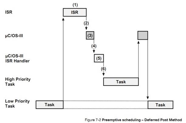
F7-2��1���жϷ�������У�����ֱ�ӷ����ź�������Ϣ���������Ƚ��ź�������Ϣ�����ⲿ��Ϣ���У��������жϴ�������
F7-2��1��The
ISR services the device and, instead of signaling or sending the message to the
task, ��C/OS-III (through the POST call) places the post call into a special
queue and makes a very high-priority task (actually the highest-possible
priority) ready to run. This task is called the ISR Handler Task.
F7-2
��3���� ISR ���������Ĺ���ʱ���Ͱ� CPU ��ʹ��Ȩ���� uC/OS-III��
F7-2
��3��When the ISR completes its work, it makes a service call to
��C/OS-III.
F7-2��3��uC/OS-III ����һЩ������
F7-2��4����Ϊ�жϴ�����������uC/OS-III �� CPU ��ʹ��Ȩ��������
F7-2��4��Since
the ISR made the ISR Handler Task ready to run, ��C/OS-III switches to that
task.
F7-2��5��uC/OS-III ����һЩ������
F7-2��6) �жϴ��������ⲿ��Ϣ�����е���Ϣ�Ƴ��������ύ����Ӧ�������������ͽ����������Ϣ�ύ���жϼ����������ʹ�����ַ�����Ŀ����Ϊ�˼�С���ж�ʱ�䣨����� 9 �£�������Ϣ����Ϊ��ʱ��uC/OS-III ���жϴ�������Ӿ����������Ƴ���Ȼ��ִ�о��������е�������ȼ�����
F7-2��6) The ISR Handler Task then removes the post call from the
message queue and reissues the post. This time, however, it does it at the task
level instead of the ISR level. The reason this extra step is performed is to
keep interrupt disable time as small as possible. See Chapter 9, ��Interrupt
Management�� on page 157 to find out more on the subject. When the queue is
emptied, ��C/OS-III removes the ISR Handler Task from the ready list and
switches to the task that was signaled or sent a message.
�������������ʱ�ᷢ�����ȣ�
Scheduling
occurs at scheduling points and nothing special must be done in the application
code since scheduling occurs automatically based on the conditions described
below.
����ǻ�����Ϣ����һ������
A
task signals or sends a message to another task:
��������ύ������ OS???Post()�������ź�������Ϣ����������ʱ���ȷ�����������
OS???Post()�����Ľ���ʱ������ע������Щ����£������Dz��ᷢ���ģ���
OS_OPT_POST_NO_SCHED �Ŀ�ѡ��������
This
occurs when the task signaling or sending the message calls one of the post
services, OS???Post(). Scheduling occurs towards the end of the OS???Post()
call. Note that scheduling does not occur if one specifies (as part of the post
call) to not invoke the scheduler (i.e., set the option argument to
OS_OPT_POST_NO_SCHED).
������� OSTimeDly()�� OSTimeDlyHMSM():
A
task calls OSTimeDly() or OSTimeDlyHMSM():
�����ʱ�������� 0�����ȷ��������Ȼ��ڸ������������к�����ִ�С�
If
the delay is non-zero, scheduling always occurs since the calling task is
placed in a list waiting for time to expire. Scheduling occurs as soon as the
task is inserted in the wait list.
�������ȴ����¼�������ʱ
A
task waits for an event to occur and the event has not yet occurred:
�� OS???Pend()������ʱ�����յ����¼�������ʱ������ͻᱻ�Ƴ��ȴ����С�Ȼ�������ѡ������б������ȼ���ߵ�����ִ�С�{�Ƴ��ȴ����е�����һ�����Ǿ���״̬����Ϊ����������ֹͣ�����У�Ч���ǿ��Ե��ӵġ�}
This
occurs when one of the OS???Pend() functions are called. The task is placed in
the wait list for the event and, if a non-zero timeout is specified, then the
task is also inserted in the list of tasks waiting to timeout. The scheduler is
then called to select the next most important task to run.
����ȡ������
If
a task aborts a pend:
һ��������Ա�ȡ����������һ��������� OS???PendAbort()���������Ƴ��ȴ��б���ʱ���ȷ�����
A
task is able to abort the wait (i.e., pend) of another task by calling
OS???PendAbort(). Scheduling occurs when the task is removed from the wait list
for the specified kernel object.
��������
If a
task is created:
�µ�������ʱ���ȷ�����
The
newly created task may have a higher priority than the task��s creator. In this
case, the scheduler is called.
����ɾ��
If a
task is deleted:
��һ������ɾ��ʱ���ȷ�����
When
terminating a task, the scheduler is called if the current task is deleted.
�ں˶���ɾ��
If a
kernel object is deleted:
�������ȴ����ں˶���ɾ��ʱ���¼���־�顢�ź�������Ϣ���С�mutex �����ں˶�����Щ����Ϳ��ܱ�������Ȼ����ȷ�����
If
you delete an event flag group, a semaphore, a message queue, or a mutual
exclusion semaphore, if tasks are waiting on the kernel object, those tasks
will be made ready to run and the scheduler will be called to determine if any
of the tasks have a higher priority than the task that deleted the kernel
object.
����ı����������ȼ���������������ȼ�
A
task changes the priority of itself or another task:
������ı��������ȼ��������������ȼ�ʱ�����ȷ�����
The
scheduler is called when a task changes the priority of another task (or
itself) and the new priority of that task is higher than the task that changed
the priority.
������ͨ������ OSTaskSuspend()ֹͣ����
A
task suspends itself by calling OSTaskSuspend():
��������� OSTaskSuspend()ֹͣ����ʱ�����ȷ�����
The
scheduler is called since the task that called OSTaskSuspend() is no longer
able to execute, and must be resumed by another task.
������� OSTaskResume()�ָ�����ֹͣ�˵�����
A
task resumes another task that was suspended by OSTaskSuspend():
������� OSTaskResume()�ָ�����ֹͣ�˵�����ʱ�����ȷ�����
The
scheduler is called if the resumed task has a higher priority than the task
that calls OSTaskResume().
�˳��жϷ������
At
the end of all nested ISRs:
���˳��жϷ������ʱ�����ȷ�������������£�����������OSIntExit()������ʼ���ȶ����� OSSched()��
The
scheduler is called at the end of all nested ISRs to determine whether a more
important task is made ready to run by one of the ISRs. The scheduling is
actually performed by OSIntExit() instead of OSSched().
ͨ������ OSSchedUnlock()������������
The
scheduler is unlocked by calling OSSchedUnlock():
���� OSSchedLock()�������������ȷ�������Ҫע����ǣ������������Ա�Ƕ�ף���������������ڼ���������
The
scheduler is unlocked after being locked. Lock the scheduler by calling
OSSchedLock(). Note that locking the scheduler can be nested and the scheduler
must be unlocked a number of times equal to the number of locks.
���� OSSchedRoundRobinYield()��������˷��������ʱ��Ƭ
A
task gives up its time quanta by calling OSSchedRoundRobinYield():
�ٶ������������ͬ�����ȼ����������е���������˷������
��ʱ��Ƭ�����ȷ�����
This
assumes that the task is running alongside with other tasks at the same
priority and the currently running task decides that it can give up its time
quanta and let another task run.
�û����� OSSched()
The
user calls OSSched():
�û�������� OSSched()ʱ�����ȷ����������� OS???Post()����ʱ���ò���Ϊ�� OS_OPT_POST_NO_SCHED���¼��ڱ��ύ�����õ���������Ȼ���������һ�����ύ����¼����������һ���¼��ύʱ�ŵ��õ�������{��Ϊ��һ���¼����ύʱ���������ͻᷢ�����ȡ������û�������
OS_OPT_POST_NO_SCHED ���û�һ�����ύ����¼���ֻ����һ�η������ȡ�}
The
application code can call OSSched() to run the scheduler. This only makes sense
if calling OS???Post() functions and specifying OS_OPT_POST_NO_SCHED so that
multiple posts can be accomplished without running the scheduler on every post.
Of course, in the above situation, the last post can be a post without the
OS_OPT_POST_NO_SCHED option.
�������������ͬ�����ȼ�ʱ��uC/OS-III ����ÿ���������й涨��ʱ��Ƭ��������û��������������ʱ��Ƭʱ����������Ը�ط���CPU��uC/OS-III ��������������ʱ�������߹ر�ѭ����ת���ȡ�
When
two or more tasks have the same priority, ��C/OS-III allows one task to run for
a predetermined amount of time (called a Time Quanta) before selecting another
task. This process is called Round-Robin Scheduling or Time Slicing. If a task
does not need to use its full time quanta it can voluntarily give up the CPU so
that the next task can execute. This is called Yielding. ��C/OS-III allows the
user to enable or disable round robin scheduling at run time.
ͼ F7-3 ����ͬ���ȼ����������е�ʱ��ͼ����ͼ�����������ȼ���Ϊ X ������Ϊ��˵����ʱ��Ƭ�ij���Ϊ 4��
Figure
7-3 shows a timing diagram with tasks running at the same priority. There are
three tasks that are ready to run at priority ��X��. For sake of illustration,
the time quanta occurs every 4th clock tick. This is shown as a darker tick
mark.
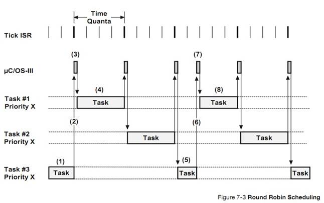
F7-3��1������ 3 ���ڱ����С������ʱ���ڣ�ʱ���жϷ����������� 3 ��û�е��ڡ�
F7-3(1) Task #3 is executing. During
that time, tick interrupts occur but the time quanta have not expired yet for
Task #3.
F7-3��2������ 3 ��������ʣ�µ�ʱ��Ƭ��
F7-3(2) On the 4th tick interrupt,
the time quanta for Task #3 expire.
F7-3��3��uC/OS-III �ָ����� 1����Ϊ���Ƕ��������� 3 ����һ������
F7-3(3) ��C/OS-III resumes Task #1
since it was the next task in the list of tasks at priority ��X�� that was ready
to run.
F7-3��4������ 1 ��ִ��ֱ�����������ʱ��Ƭ���ڡ�
F7-3(4) Task #1 executes until its
time quanta expires (i.e., after four ticks).
F7-3��5������ 3 ���ڱ����С������ʱ���ڣ�ʱ���жϷ����������� 3 ��û�е��ڡ�
F7-3��6������ 3 ��������ʣ�µ�ʱ��Ƭ��
F7-3��7����Ȥ�����鷢���ˣ�uC/OS-III �������������� 1 ��ʱ��Ƭ����Ϊ 4 ��ʱ������ʣ��ʱ��Ƭ�ļ�����ÿ��ʱ���жϵݼ������ڵ�4 ��ʱ���жϷ���ʱʱ��Ƭ���ڡ������� 1 ����ʱ����������ʱ���ֵģ�������ʵ������ʱ��Ƭ����һ��ʱ����
F7-3(7) Here Task #3 executes but
decides to give up its time quanta by calling the ��C/OS-III function
OSSchedRoundRobinYield(), which causes the next task in the list of tasks ready
at priority ��X�� to execute. An interesting thing occurred when ��C/OS-III
scheduled Task #1. It reset the time quanta for that task to four ticks so that
the next time quanta will expire four ticks from this point.
F7-3��8������ 1 ִ��
F7-3(8) Task #1 executes for its full
time quanta.
uC/OS-III
�����û�����������ʱ��ʱ��Ƭ�ij��ȣ�ͨ�� OSSchedRoundRobinCfg()�������¼ A�����������Ҳ�������ڿ�����ر�ѭ����ת���ȡ�
��C/OS-III
allows the user to change the time quanta at run time through the
OSSchedRoundRobinCfg() function (see Appendix A, ����C/OS-III API Reference
Manual�� on page 375). This function also allows round robin scheduling to be
enabled/disabled, and the ability to change the default time quanta.
uC/OS-III
�����û�Ϊÿ���������ò�ͬ��ʱ��Ƭ����ͬ����������в�ͬ��ʱ��Ƭ����������ʱ����ʱ��Ƭ���ȱ����á�Ҳ����������ʱ����OSTaskTimeQuantaSet()�ġ�
��C/OS-III
also enables the user to specify the time quanta on a per-task basis. One task
could have a time quanta of 1 tick, another 12, another 3, and yet another 7,
etc. The time quanta of a task is specified when the task is created. The time
quanta of a task may also be changed at run time through the function
OSTaskTimeQuantaSet().
ͨ��������������ɵ��ȹ��ܣ�OSSched()�� OSIntExit()��OSSched()���������ã�OSIntExit()���жϼ������á��������������� OS_CORE.C �ж��塣
Scheduling
is performed by two functions: OSSched() and OSIntExit(). OSSched() is called
by task level code while OSIntExit() is called by ISRs. Both functions are
found in OS_CORE.C.
ͼ 7-1 �����˵��������õ��������ݽṹ��λӳ����;����б���
Figure
7-1 illustrates the two sets of data structures that the scheduler uses; the
priority ready bitmap and the ready list as described in Chapter 6, ��The Ready
List�� on page 123.
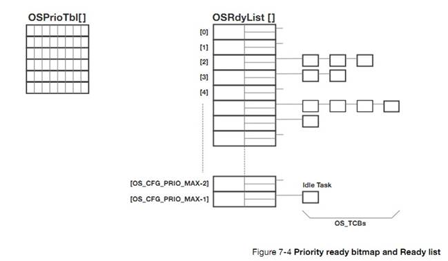
7-4-1 OSSched()
�����������ȵ�α���롣
The
pseudo code for the task level scheduler, OSSched() is shown in Listing 7-1.
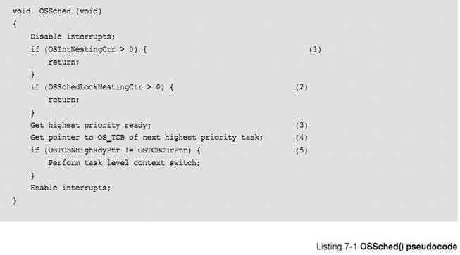
L7-1��1����ΪҪ������ȳ����жϡ�OSSched()����ȷ���Լ����DZ��жϷ��������ã���Ϊ���������ȳ����жϼ���������� OSIntExit()��
L7-1(1) OSSched() starts by making
sure it is not called from an ISR as OSSched() is the task level scheduler.
Instead, an ISR must call OSIntExit(). If OSSched() is called by an ISR,
OSSched() simply returns.
L7-1��2���ڶ�����ȷ��������û�б���������������������Ͳ������е��������������Ϸ��ء�
L7-1(2) The next step is to make sure
the scheduler is not locked. If the code calls OSSchedLock() the user does not
want to run the scheduler and the function just returns.
L7-1��3��OSSched()ͨ��ɨ��λӳ���
OSPrioTbl[]�ҵ������б������ȼ���ߵ�λ��������½� 6��
L7-1(3) OSSched() determines the
priority of the highest priority task ready by scanning the bitmap OSPrioTbl[]
as described in Chapter 6, ��The Ready List�� on page 123.
L7-1��4��ȷ�������ȼ��������� OSRdyList[]����ȡ�ü�¼�е��� TCB��OSRdyList[highest priority].HeadPtr����������Ϊֹ���Ѿ�֪�����ĸ�����Ҫ�л�Ϊ����״̬���ر�ģ�OSTCBCurPtr ָ����ǵ�ǰ����� TCB��OSTCBHighRdyPtr ָ����ǽ�Ҫ���л��� TCB��
L7-1(4) Once it is known which
priority is ready, index into the OSRdyList[] and extract the OS_TCB at the
head of the list (i.e., OSRdyList[highest priority].HeadPtr). At this point, it
is known which OS_TCB to switch to and which OS_TCB to save to as this was the
task that called OSSched(). Specifically, OSTCBCurPtr points to the current
task��s OS_TCB and OSTCBHighRdyPtr points to the new OS_TCB to switch to.
L7-1��5�����������е�������ȼ�����Ϊ��ǰ�������е�����ʱ��OSTCBCurPtr!=OSTCBHighRdyPtr�������������������л���Ȼ���ڿ��жϡ�
L7-1(5)
If the user is not attempting to switch to the same task that is currently
running, OSSched() calls the code that will perform the context switch (see
Chapter 8, ��Context Switching�� on page 147). As the code indicates, however,
the task level scheduler calls a task-level function to perform the context switch.
ע����ǣ�����ʱ���������л��������ڹ��жϵ�״̬�µġ����DZ�Ҫ����Ϊ��Щ������ԭ���Եġ�
Notice
that the scheduler and the context switch runs with interrupts disabled. This
is necessary because this process needs to be atomic.
7-4-2 OSIntExit()
������ ISR ���ĵ��������� OSIntExit()���б� 7-2 ��ʾ����Ҫע�����ٶ��������� OSIntExit()֮���жϱ��رա�
The
pseudo code for the ISR level scheduler, OSIntExit() is shown in Listing 7-2.
Note that interrupts are assumed to be disabled when OSIntExit() is called.
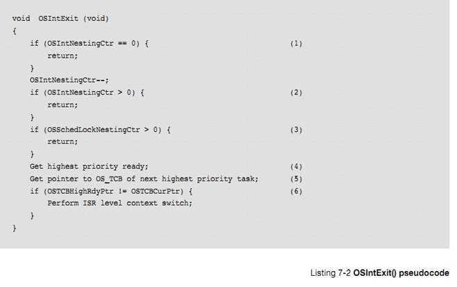
L7-2��1��OSIntExit()��ʼʱȷ���ж�Ƕ����Ϊ 0��{���Ϊ 0 �Ļ�����ô�������� OSIntNestingCtr--�ͻᷢ�������}
L7-2(1) OSIntExit() starts by making sure
that the call to OSIntExit() will not cause OSIntNestingCtr to wrap around.
This would be extremely and unlikely occurrence, but not worth taking a chance
that it might.
L7-2��2��OSInrExit()��
OSIntNestingCtr �ݼ����� OSIntNestingCtr ��Ϊ 0 ʱ�ء�ȷ���ú������ڵ�һ�� ISR ��ִ�С��������жϳ���δ������ʱ�Ͳ������е�������
L7-2(2) OSIntExit() decrements the
nesting counter as OSIntExit() is called at the end of an ISR. If all ISRs have
not nested, the code simply returns. There is no need to run the scheduler
since there are still interrupts to return to.
L7-2��3��OSIntExit()���������Ƿ��������������OSIntExit() �������е����������ص��ж�ǰ������
L7-2(3) OSIntExit() checks to see
that the scheduler is not locked. If it is, OSIntExit() does not run the
scheduler and simply returns to the interrupted task that locked the scheduler.
L7-2��4�������ǵ�һ���ж��ҵ�����û�б���ʱ���������ȼ���ߵ�����
L7-2(4) Finally, this is the last
nested ISR (we are returning to task-level code) and the scheduler is not
locked. Therefore, we need to find the highest priority task that needs to run.
L7-2��5���� OSRdyList[]�л��������ȼ��� TCB��
L7-2(5) Again, we extract the highest
priority OS_TCB from OSRdyList[].
L7-2��6�����������ȼ����������ǵ�ǰ�������е�����uC/OS-III ��ִ���жϼ����������л����жϼ��л��������Ѿ����жϿ�ʼʱ�������ˣ�������ֱ���л���������Щ�ڵ� 8 ������ϸ���ܡ�
L7-2(6) If the highest-priority task
is not the current task ��C/OS-III performs an ISR level context switch. The ISR
level context switch is different as it is assumed that the interrupted task��s
context was saved at the beginning of the ISR and it is only left to restore
the context of the new task to run. This is described in Chapter 8, ��Context
Switching�� on page 147.
7-4-3 OS_SchedRoundRobin()
��ͬһ���ȼ����ж������һ�������ʱ��Ƭ������uC/OS-III �ͻ�����ͬ���ȼ�����������OS_SchedRoundRobin()����ִ�����ֲ����ģ�����OSTimeTick()���� OS_IntQTask()���á�OS_SchedRoundRobin()�� OS_CORE.C �ж��塣
When
the time quanta for a task expires and there are multiple tasks at the same
priority, ��C/OS-III will select and run the next task that is ready to run at
the current priority. OS_SchedRoundRobin() is the code used to perform this
operation. OS_SchedRoundRobin() is either called by OSTimeTick() or
OS_IntQTask(). OS_SchedRoundRobin() is found in OS_CORE.C.
����ѡ��ֱ���ύ��ʽʱ��OS_SchedRoundRobin()�� OSTimeTick() ���á���ѡ���ӳ��ύ��ʽʱ��OS_SchedRoundRobin()��OS_IntQTask()���á�
OS_SchedRoundRobin()
is called by OSTimeTick() when you selected the Direct Method of posting (see
Chapter 9, ��Interrupt Management�� on page 157). OS_SchedRoundRobin() is called
by OS_IntQTask() when selecting the Deferred Post Method of posting, described
in Chapter 8.
OS_SchedRoundRobin()��α�������б� 7-3 ��ʾ
The
pseudo code for the round-robin scheduler is shown in Listing 7-3.
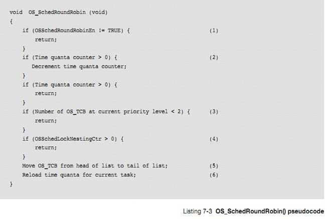
L7-3��1��OS_SchedRoundRobin()��ʼʱ��ȷ��ѭ����ת�����Ѿ���ʹ�ܡ�������ͨ������ OSSchedRoundRobinCfg()����ѭ����ת���ȣ���
L7-3(1) OS_SchedRoundRobin() starts
by making sure that round robin scheduling is enabled. Recall that to enable
round robin scheduling, one must call OSSchedRoundRobinCfg().
L7-3��2��ʱ��Ƭ����ֵ��פ����������������� TCB �У�ÿ��ʱ���ж�ʱ�����ݼ���������ֵ��Ϊ 0 ʱ OS_SchedRoundRobin()���ء�
L7-3(2) The time quanta counter,
which resides inside the OS_TCB of the running task, is decremented. If the
value is still non-zero then OS_SchedRoundRobin() returns.
L7-3��3����ʱ��Ƭ����ֵΪ 0 ʱ������Ƿ�������ͬ���ȼ�����ȴ������С����û�У��ͷ��ء�
L7-3(3) Once the time quanta counter
reaches zero, check to see that there are other ready-to-run tasks at the
current priority. If there are none, return. Round robin scheduling only
applies when there are multiple tasks at the same priority and the task doesn��t
completes its work within its time quanta.
L7-3��4��������������ʱ��OS_SchedRoundRobin()���ء�
L7-3(4) OS_SchedRoundRobin() also
returns if the scheduler is locked.
L7-3��5������ǰ�����ʱ��Ƭ���ڣ�OS_SchedRoundRobin()����ǰ����� TCB �ƶ��������ȼ����е�ĩβ����ͷ���Ƶ�β������
L7-3(5) Next, OS_SchedRoundRobin()
move the OS_TCB of the current task from the head of the ready list to the end.
L7-3��6���ڸ����ȼ���¼�����ײ��������ʱ��Ƭֵ�����뵽����ÿ�����������Լ���ʱ��Ƭֵ��������ʱ�����û�ͨ��OSTaskTimeQuantaSet()���ã��������ֵΪ 0��uC/OS-III �ͼٶ�ʱ��ƬֵΪĬ��ֵOSSchedRoundRobinDfltTimeQuanta��
L7-3(6)
The time quanta for the task at the head of the list are loaded. Each task may
specify its own time quanta when the task is created or through
OSTaskTimeQuantaSet(). If specifying 0, ��C/OS-III assumes the default time
quanta, which corresponds to the value in the variable
OSSchedRoundRobinDfltTimeQuanta.
uC/OS-III
�ǿ���ռ�ĵ�����������������ִ�����ȼ���ߵľ�������
��C/OS-III
is a preemptive scheduler so it will always execute the highest priority task
that is ready to run.
uC/OS-III
���ж�����������ͬ�����ȼ�����ʱ�������Ա�����Ϊѭ����ת���ȡ�
��C/OS-III
allows for multiple tasks at the same priority. If there are multiple
ready-to-run tasks, ��C/OS-III will round robin between these tasks.
���ȷ�����һЩ�ض���ʱ��㡣
Scheduling
occurs at specific scheduling points, when the application calls ��C/OS-III
functions.
uC/OS-III
�� 2 �ֵ��ȷ�ʽ��OSSched()����������OSIntExit() �������жϼ���
��C/OS-III
has two schedulers: OSSched(), which is called by task-level code, and
OSIntExit() called at the end of each ISR.
8���������л�
�� uC/OS-III ת��ִ����һ�������ʱ���������˵�ǰ�����CPU �Ĵ�������ջ������������ĵĶ�ջ�� CPU �Ĵ������� CPU��������̽����������л���
When
��C/OS-III decides to run a different task (see Chapter 7, ��Scheduling�� on page
133), it saves the current task��s context, which typically consists of the CPU
registers, onto the current task��s stack and restores the context of the new
task and resumes execution of that task. This process is called a Context
Switch.
�������л���ҪһЩ��֧��CPU �ļĴ���Խ�࣬��֧Խ���������л���ʱ�����ȡ�����ж��ٸ� CPU �Ĵ�����Ҫ���洢�����ˡ�
Context
switching adds overhead. The more registers a CPU has, the higher the overhead.
The time required to perform a context switch is generally determined by how
many registers must be saved and restored by the CPU.
�������л����ֵĴ�������ֲ uC/OS-III ʱ���д�ġ��ò��ִ���Ҫ�����ڴ���������Щ���뱻���� C �ͻ�������ļ��У�OS_CPU.H��OS_CPU_C.C��OS_CPU_A.ASM���½� 18����ֲ uC/OS-III������ϸ���ܣ������ݲ�ͬ�ܹ��� CPU����ֲ uC/OS-III ʱ��Ҫע��ܶ�ϸ�ڡ�
The context
switch code is generally part of a processor��s port of ��C/OS-III. A port is the
code needed to adapt ��C/OS-III to the desired processor. This code is placed in
special C and assembly language files: OS_CPU.H, OS_CPU_C.C and OS_CPU_A.ASM.
Chapter 18, ��Porting ��C/OS-III�� on page 335, Porting ��C/OS-III provides more
details on the steps needed to port ��C/OS-III to different CPU architectures.
������½��У������ڳ����� CPU �ܹ��������������л��Ĺ�����ͼ 8-1����� CPU ������ 16 �������Ĵ���(R0
�� R15)��һ���ж϶�ջ�Ĵ�����һ��״̬�Ĵ���{�� 18 ���Ĵ�����R0 ��
R15,R14"��SR}��ÿ���Ĵ������� 32 λ�ģ����� 16 �������Ĵ������ܴ洢���ݻ��ַ��ָ��ָ��Ĵ����� R15��������ջָ��Ĵ����� R14 �� R14"��
In
this chapter, we will discuss the context switching process in generic terms
using a fictitious CPU as shown in Figure 8-1. Our fictitious CPU contains 16
integer registers (R0 to R15), a separate ISR stack pointer, and a separate
status register (SR). Every register is 32 bits wide and each of the 16 integer
registers can hold either data or an address. The program counter (or
instruction pointer) is R15 and there are two separate stack pointers labeled
R14 and R14��.
R14
��ָ������Ķ�ջ��ָ�� TSP��R14"��ָ�� ISR �Ķ�ջ��ָ�� ISP����
CPU ���յ�һ���ж��Զ��л��� ISR ��ջ��{Ҳ���Ǵ������ж��������ڴ����жϵĶ�ջ}
R14
represents a task stack pointer (TSP), and R14�� represents an ISR stack pointer
(ISP). The CPU automatically switches to the ISR stack when servicing an
exception or interrupt. The task stack is accessible from an ISR (i.e., we can
push and pop elements onto the task stack when in an ISR), and the interrupt
stack is also accessible from a task.
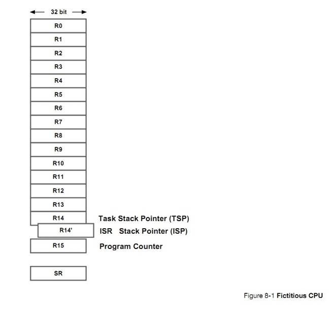
�� uC/OS-III �У������л�ʱ�Ķ�ջ�����������жϷ���ʱ�����������е� CPU �Ĵ����������档���Ǽٶ������ջ�е���Ϣ��Ҫ�����뵽 CPU �У���ͼ 8-2��
In
��C/OS-III, the stack frame for a ready task is always setup to look as if an
interrupt has just occurred and all processor registers were saved onto it.
Tasks enter the ready state upon creation and thus their stack frames are
pre-initialized by software in a similar manner. Using our fictitious CPU,
we��ll assume that a stack frame for a task that is ready to be restored is shown
in Figure 8-2.
TSP
ָ�������ջ�����һ��������ļĴ���������ָ��Ĵ�����״̬�Ĵ��������ȱ������������ջ�С���ʵ�ϣ����жϷ���ʱ��Щ�DZ� CPU �Զ�ִ�еġ������ļĴ���ͨ��������ѹ�������ջ��TSP ���ᱻ���浽��ջ�����ᱻ���浽����� TCB��
The
task stack pointer points to the last register saved onto the task��s stack. The
program counter and status registers are the first registers saved onto the
stack. In fact, these are saved automatically by the CPU when an exception or
interrupt occurs (assuming interrupts are enabled) while the other registers
are pushed onto the stack by software in the exception handler. The stack
pointer (R14) is not actually saved on the stack but instead is saved in the
task��s OS_TCB.
ISP
ָ��ǰ�ж϶�ջ�Ķ��������жϷ������ִ��ʱ���������� R14"��Ϊ��ջָ������ָ�����;ֲ�������
The
interrupt stack pointer points to the current top-of-stack for the interrupt
stack, which is a different memory area. When an ISR executes, the processor
uses R14�� as the stack pointer for function calls and local arguments.
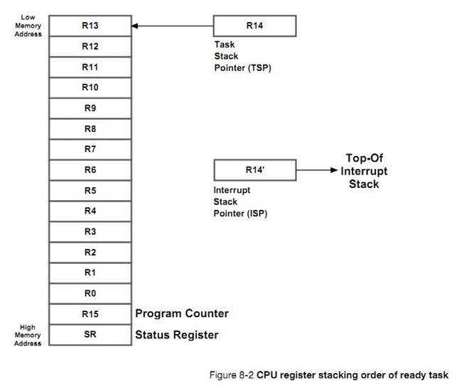
�������������л���ʽ��һ��������һ�����жϼ��������л�ͨ������OSCtxSw()ʵ�֣�ʵ�������DZ��� OS_TASK_SW()���õġ�
There
are two types of context switches: one performed from a task and another from
an ISR. The task level context switch is implemented by the code in OSCtxSw(),
which is actually invoked by the macro OS_TASK_SW(). A macro is used as there
are many ways to invoke OSCtxSw() such as software interrupts, trap
instructions, or simply calling the function.
�жϼ��л�ͨ������ OSIntCtxSw()ʵ�֡������û������д�ģ������� OS_CPU_A.ASM��
The
ISR context switch is implemented by OSIntCtxSw(). The code for both functions
is typically written in assembly language and is found in a file called
OS_CPU_A.ASM.
����һ�������ȼ�����������Ҫ��ִ�У��������������OSCtxSw()��ͼ 8-3 ��ʾ���ڵ��� OSCtxSw() ֮ǰ��һЩ���������ݽṹ��
OSCtxSw()
is called when the task level scheduler (OSSched()) determines that a new high
priority task needs to execute. Figure 8-3 shows the state of several ��C/OS-III
variables and data structures just prior to calling OSCtxSw().
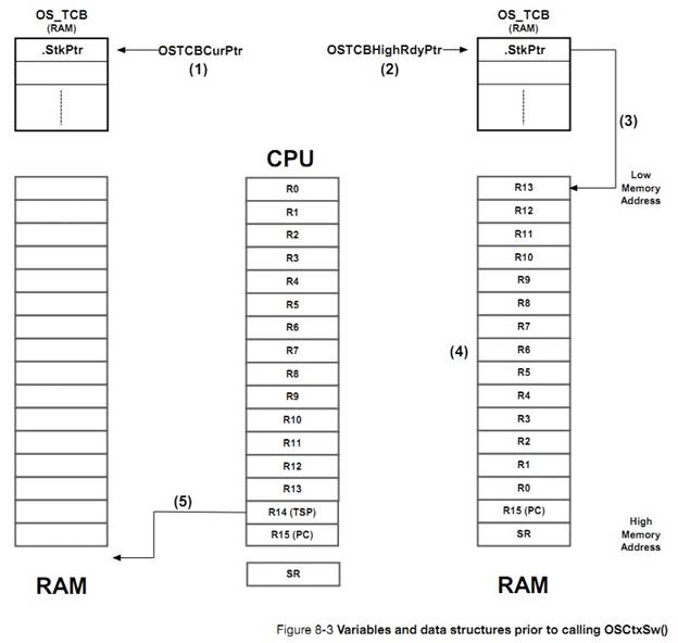
F8-3��1��OSTCBCurPtr ָ���˵�ǰ������������� OS_TCB��Ȼ��
OSSchedule()�����á�
F8-3(1) OSTCBCurPtr points to the
OS_TCB of the task that is currently running and that called OSSched().
F8-3��2��ͨ�� OSTCBHighRdyPtr��OSSched()�ҵ���Ҫ�����������OS_TCB��
F8-3(2) OSSched() finds the new task
to run by having OSTCBHighRdyPtr point to its OS_TCB.
F8-3��3��OSTCBHighRdyPtr->StkPtr ָ��Ҫ�����������ջ�Ķ�����{�ٶ���ջ�Ǵ��ڴ�ߵ�ַ��ص�ַ������}
F8-3(3) OSTCBHighRdyPtr->StkPtr
points to the top of stack of the new task to run.
F8-3��4��ִ��������������л�ʱ�����е� CPU �Ĵ��������浽�������ջ�����ڱ���������ĵ�ǰ״̬������������Ա��ָ���
F8-3(4) When ��C/OS-III creates or
suspends a task, it always leaves the stack frame to look as if an interrupt
just occurred and all the registers saved onto it. This represents the expected
state of the task so it can be resumed.
F8-3��5������ OSSched()�� CPU �� TSP ��ָ������Ķ�ջ������OSCtxSw()�ı�������ʽ��TSP Ҳ����ָ�� OSCtxSw()�ķ��ص�ַ��
F8-3(5) The CPU��s stack pointer
points within the stack area (i.e., RAM) of the task that called OSSched(). Depending
on how OSCtxSw() is invoked, the stack pointer may be pointing at the return
address of OSCtxSw().
ͼ 8-4 չʾ�� OSCtxSw()ʵ���������л�����ز��衣
Figure
8-4 shows the steps involved in performing the context switch as implemented by
OSCtxSw().
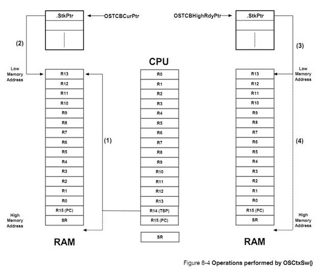
F8-4��1��OSCtxSw()��ʼִ�У�����״̬�Ĵ����ͳ���ָ��Ĵ�������ǰ�������ջ�������˳�����жϷ���ʱ CPU ����Ĵ�����˳����ͬ���ٶ� SR ����ջ��Ȼ�������Ĵ�����ջ��
F8-4(1) OSCtxSw() begins by saving
the status register and program counter of the current task onto the current
task��s stack. The saving order of register depends on how the CPU expects the
registers on the stack frame when an interrupt occurs. In this case, it is
assumed that the SR is stacked first. The remaining registers are then saved
onto the stack.
F8-4��2��������ֹͣʱ��OSCtxSw()���� CPU �� TSP ���������OS_TCB
�У����仰˵��OSTCBCurPtr->StkPtr=R14��
F8-4(2) OSCtxSw() saves the contents
of the CPU��s stack pointer into the OS_TCB of the task being suspended. In
other words, OSTCBCurPtr->StkPtr = R14.
F8-4��3��Ȼ�� OSCtxSw()��������
OS_TCB �Ķ�����ַ���� CPU ��TSP �С����仰˵��R14=OSTCBCurPtr->StkPtr��
F8-4(3) OSCtxSw() then loads the CPU
stack pointer with the saved top-of-stack from the new task��s OS_TCB. In other
words, R14 = OSTCBHighRdyPtr->StkPtr.
F8-4��4�����OSCtxSw()���������ջ�� R13~~R0 ���������� CPU �Ĵ�������Ȼ��ʱ�Ļ� TSP ָ�� PC����ͼ����ͨ��һ���жϷ���ָ��{�������е� IRET}������ָ��Ĵ�����״̬�Ĵ������ָ��� CPU �ļĴ����С�
F8-4(4) Finally, OSCtxSw() retrieves
the CPU register contents from the new stack. The program counter and status
registers are generally retrieved at the same time by executing a return from
interrupt instruction.
�� ISR �о����˸����ȼ����� B��ISR
����ʱ������ص��ж�ǰ������ A������ֱ��ת��ִ�и����ȼ����� B����ʱ�������жϲ���ʱ�Ѿ������� A ��״̬���������� A �Ķ�ջ�У����� ISR ����ʱ�����ٱ������� A ��״̬������ֱ���������� B ��
CPU �Ĵ�����Ӳ��CPU �Ĵ����м��ɡ�����
OSIntCtxSw()ִ�иò�����ͼ 8-5 ��ʾ���ڵ���
OSIntCtxSw() ֮ǰ��һЩ���������ݽṹ��
OSIntCtxSw()
is called when the ISR level scheduler (OSIntExit()) determines that a new high
priority task is ready to execute. Figure 8-5 shows the state of several
��C/OS-III variables and data structures just prior to calling OSIntCtxSw().
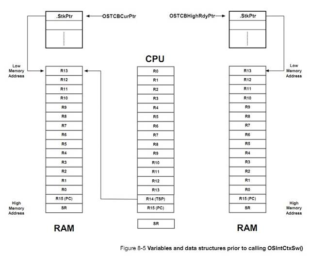
�ڽ��� ISR ֮ǰ CPU �Ĵ����ᱻ���������� A �Ķ�ջ�С���ˣ�OSTCBCurPtr->StkPtr ������ָ�������Ĵ�����ָ�롣
��C/OS-III
assumes that CPU registers are saved onto the task��s stack at the beginning of
an ISR (see Chapter 9, ��Interrupt Management�� on page 157). Because of this,
notice that OSTCBCurPtr->StkPtr contains a pointer to the top-of-stack
pointer of the task being suspended (the one on the left). OSIntCtxSw() does
not have to worry about saving the CPU registers of the suspended task since
that is already finished.
ͼ 8-6 ��ʾ�� OSIntCtxSw()ִ���������� B �� CPU �Ĵ������衣
�ⲿ�ֵIJ���� OSCtxSw()���°벿�ֲ�����һ���ġ�
Figure
8-6 shows the operations performed by OSIntCtxSw() to complete the second half
of the context switch. This is exactly the same process as the second half of
OSCtxSw().
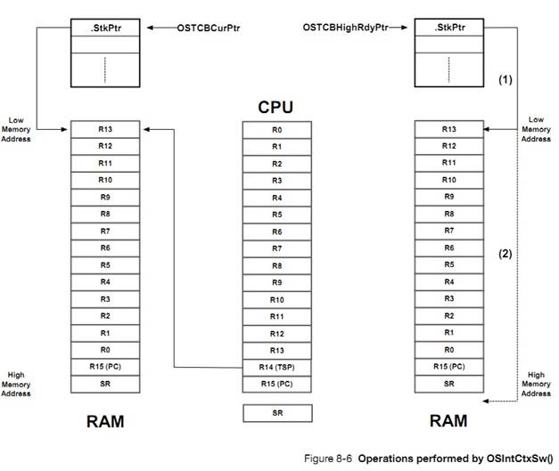
F8-6
��1��OSIntCtxSw()�������� OS_TCB �Ķ�����ջ��ֵַ����CPU �е� TSP���� R14=OSTCBHighRdyPtr->StkPtr��
F8-6(1) OSIntCtxSw() loads the CPU
stack pointer with the saved top-of-stack from the new task��s OS_TCB. R14 =
OSTCBHighRdyPtr->StkPtr.
F8-6��2��Ȼ�� OSIntCtxSw()���¶�ջ������������뵽 CPU �Ĵ����С�ͨ��һ���жϷ���ָ�����ָ��Ĵ�����״̬�Ĵ��������롣
F8-6(2) OSIntCtxSw() then retrieves
the CPU register contents from the new stack. The program counter and status
registers are generally retrieved at the same time by executing a return from
interrupt instruction.
�������л��������������ݣ��������������ݣ���������������ݡ������л�ʱ��ͨ������ OSSched()ʵ�֡��жϼ��л�ʱ��ͨ������ OSIntExit()ʵ�֡�
A
context switch consists of saving the context (i.e., CPU registers) associated
with one task and restoring the context of a new, higher-priority task.
The new
task to be switched to is determined by OSSched() when a context switch is
initiated by task level code, and OSIntExit() when initiated by an ISR.
OSSched()�е��� OSCtxSw()ʵ���������л���OSIntExit()�е���SIntCtxSw()ʵ���������л���Ȼ����OSIntCtxSw()ֻ�������������л��ĵڶ����֣���Ϊ�ж�ʱ���ж������
CPU �Ĵ����Ѿ������浽���ж�����Ķ�ջ���ˡ�
OSCtxSw()
performs the context switch for OSSched() and OSIntCtxSw() performs the context
switch for OSIntExit(). However, OSIntCtxSw() only needs to perform the second
half of the context switch because it is assumed that the ISR saved CPU
registers upon entry to the ISR.
9���жϹ���
�ж���Ӳ�����ƣ�����֪ͨ CPU ���첽�¼����������жϱ���Ӧʱ��CPU ���沿�֣���ȫ�����Ĵ���ֵ����ת���жϷ������ISR����
An
interrupt is a hardware mechanism used to inform the CPU that an asynchronous
event occurred. When an interrupt is recognized, the CPU saves part (or all) of
its context (i.e., registers) and jumps to a special subroutine called an
Interrupt Service Routine (ISR).
ISR
��Ӧ����¼����� ISR ������ɺ���᷵���ж�ǰ�������������ȼ�������
The
ISR processes the event, and �C upon completion of the ISR �C the program either
returns to the interrupted task, or the highest priority task, if the ISR made
a higher priority task ready to run.
��ʵʱϵͳ�У����жϵ�ʱ��Խ��Խ�á���ʱ����жϿ��ܻᵼ���ж���������Ӧ���ص���������жϱ�����һ���жϡ�
In a
real-time environment, interrupts should be disabled as little as possible.
Disabling interrupts affects interrupt latency possibly causing interrupts to
be missed.
ͨ�������������ж�Ƕ�ף�����ζ�ŵ����� ISR ʱ����������һ���жϷ�����
��ʵʱϵͳ�У����Ĺ��ж�ʱ����һ����Ҫ�����ܣ����ж���Ϊ�˴����ٽ�δ��롣
Processors
generally allow interrupts to be nested, which means that while servicing an
interrupt, the processor recognizes and services other (more important)
interrupts.
Interrupts
allow a microprocessor to process events when they occur (i.e.,
asynchronously), which prevents the microprocessor from continuously polling
(looking at) an event to see if it occurred. Task level response to events is
typically better using interrupt mode as opposed to polling mode, however at
the possible cost of increased interrupt latency. Microprocessors allow
interrupts to be ignored or recognized through the use of two special
instructions: disable interrupts and enable interrupts, respectively.
One
of the most important specifications of a real-time kernel is the maximum
amount of time that interrupts are disabled. This is called interrupt disable
time. All real-time systems disable interrupts to manipulate critical sections
of code and re-enable interrupts when critical sections are completed. The
longer interrupts are disabled, the higher the interrupt latency.
�ж���Ӧʱ�䶨��Ϊ�����յ��жϵ���ʼ���� ISR �д�������ʱ�䡣ͨ�����ж�ʱ�û���������ģ�CPU �Ĵ������ᱻ�����ջ�С�
Interrupt
response is defined as the time between the reception of the interrupt and the
start of the user code that handles the interrupt. Interrupt response time
accounts for the entire overhead involved in handling an interrupt. Typically,
the processor��s context (CPU registers) is saved on the stack before the user
code is executed.
�жϻָ�ʱ�䶨��Ϊ��ִ���� ISR �����һ�����ָ�������������ʱ�䡣
Interrupt
recovery is defined as the time required for the processor to return to the
interrupted code or to a higher priority task if the ISR made such a task ready
to run.
�����ӳ�ʱ�䶨��Ϊ���жϷ������ָ�������������ʱ�䡣
Task
latency is defined as the time it takes from the time the interrupt occurs to
the time task level code resumes.
Ŀǰ�г����кܶ��ּܹ��� CPU��������ͨ���ж���ж�Դ�����磬UART �жϡ�DMA �жϡ�ADC �жϡ���ʱ���жϵȡ�
There
are many popular CPU architectures on the market today, and most processors
typically handle interrupts from a multitude of sources. For example, a UART
receives a character, an Ethernet controller receives a packet, a DMA
controller completes a data transfer, an Analog-to-Digital Converter (ADC)
completes an analog conversion, a timer expires, etc.
�ڴ��������£��жϿ����������е��ж��ύ������������ͼ 9-1 ��ʾ
�ж�������־�жϴ�������Ȼ���жϴ����������ȼ���ߵ��ж��ύ�� CPU��
In
most cases, an interrupt controller captures all of the different interrupts presented
to the processor as shown in Figure 9-1 (note that the ��CPU Interrupt
Enable/Disable�� is typically part of the CPU, but is shown here separately for
sake of the illustration).
Interrupting
devices signal the interrupt controller, which then prioritizes the interrupts
and presents the highest-priority interrupt to the CPU.
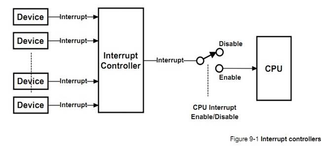
���ڵ��жϿ������������ܵģ����������ж����ȼ�����ס��Щ�жϻ����ڹ���״̬���ڴ��������£��жϿ�������ֱ���ṩ��ӦISR ��������ַ��CPU��
Modern
interrupt controllers have built-in intelligence that enable the user to
prioritize interrupts, remember which interrupts are still pending and, in many
cases, have the interrupt controller provide the address of the ISR (also
called the vector address) directly to the CPU.
���ȫ���жϱ��رգ�CPU �ͻ�����������жϿ��������ж�������Щ��������жϿ������б�����ֱ�� CPU
���¿����жϡ�
If
��global�� interrupts (i.e., the switch in Figure 9-1) are disabled, the CPU will
ignore requests from the interrupt controller, but they will be held pending by
the interrupt controller until the CPU re-enables interrupts.
CPU
�����ж�������ģʽ��
CPUs
deal with interrupts using one of two models:
���е��ж�ָ��ͬһ�� ISR
All
interrupts vector to a single interrupt handler.
ÿ���ж�ָ����Ե� ISR
Each
interrupt vectors directly to an interrupt handler.
Before
discussing these two methods, it is important to understand how ��C/OS-III
handles CPU interrupts.
�����ж�ʱ CPU ��ִ�е�һЩ���衣���У�2����3)��10����11���Ǵ������Զ���ɵġ���4��~��9�����û��� ISR �б�д��
��C/OS-III
requires that an interrupt service routine be written in assembly language.
However, if a C compiler supports in-line assembly language, the ISR code can
be placed directly into a C source file. The pseudo-code for a typical ISR when
using ��C/OS-III is shown in Listing 9-1.
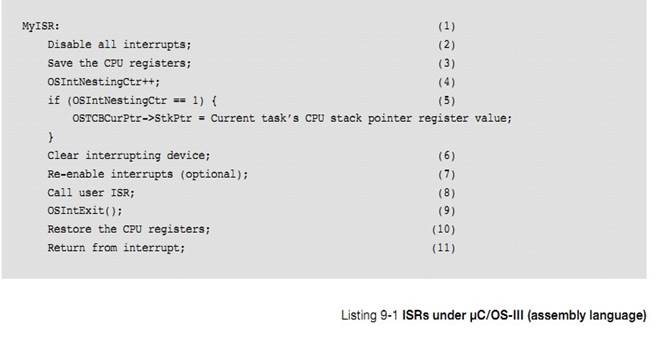
L9-1��1��ISR ͨ�����û��д�ģ�Ҳ������
C ���Ա�д��
L9-1(1) As mentioned above, an ISR is
typically written in assembly language. MyISR corresponds to the name of the
handler that will handle the interrupting device.
L9-2��2���ڽ����ٽ��֮ǰ�����жϡ���Щ�����������жϷ������ʱ���Զ����жϣ���Щ����Ҫ�û��ֶ����жϡ�
L9-1(2) It is important that all
interrupts are disabled before going any further. Some processors have
interrupts disabled whenever an interrupt handler starts. Others require the
user to explicitly disable interrupts as shown here. This step may be tricky if
a processor supports different interrupt priority levels.
However,
there is always a way to solve the problem.
L9-3��3���жϷ����������Ҫ���ľ��DZ��浱ǰ��������ĵ������ջ����Щ CPU ���Զ����ж�ǰ�����ı��浽�ж϶�ջ�������ͽ�ʡ��ʹ�ñ���������ջ��Ȼ�������� uC/OS-III���жϵ�������Ҫ�����浽�����ջ��
L9-1(3) The first thing the interrupt
handler must do is save the context of the CPU onto the interrupted task��s
stack. On some processors, this occurs automatically. However, on most
processors it is important to know how to save the CPU registers onto the
task��s stack. Save the full ��context�� of the CPU, which may also include
Floating-Point Unit (FPU) registers if the CPU used is equipped with an FPU.
Certain
CPUs also automatically switch to a special stack just to process interrupts (i.e.,
an interrupt stack). This is generally beneficial as it avoids using up
valuable task stack space. However, for ��C/OS-III, the context of the
interrupted task needs to be saved onto that task��s stack.
���������û��ר����ָ�� ISR �Ķ�ջָ��{Ҳ����
R14"}����ô������Ҫ������ģ�⡣�ر�ģ����� ISR ʱ�����浱ǰ�������ջ��Ȼ�� R14"ָ���������ж϶�ջ{Ҳ�����û�����ģ��}��
If
the processor does not have a dedicated stack pointer to handle ISRs then it is
possible to implement one in software. Specifically, upon entering the ISR,
simply save the current task stack, switch to a dedicated ISR stack, and when
done with the ISR switch back to the task stack.
��Ȼ������ζ����ҪдһЩ���ӵĴ��룬���Ƿdz����õ���Ϊû��Ҫ�ٷ���������ջ����Ŀռ䣨Ƕ�ײ����ܶ����������Ķ�ջ�ռ䣩��
Of
course, this means that there is additional code to write, however the benefits
are enormous since it is not necessary to allocate extra space on the task
stacks to accommodate for worst case interrupt stack usage including interrupt
nesting.
L9-1��4����һ�������� OSIntEnter()���� OSIntNestingCtr ��ֵ�������� OSIntNestingCtr ��ֵ��������Ч��OSIntNestingCtr �����˵�ǰ��Ƕ�ײ�����
L9-1(4) Next, either call
OSIntEnter(), or simply increment the variable OSIntNestingCtr in assembly
language. This is generally quite easy to do and is more efficient than calling
OSIntEnter(). As its name implies, OSIntNestingCtr keeps track of the interrupt
nesting level.
L9-1��5)�������Ƕ�ĵ�һ�㣬���ж�ǰ������� TSP ���浽�����OS_TCB��ָ�� OSTCBCurPtr ָ���ж�ǰ������� OS_TCB��
OSTCBCurPtr->StkPtr
����Ϊ OS_TCB ��ƫ����Ϊ 0 �ĵ�ַ��
{OSTCBCurPtr->StkPtr
�ȼ��� ��ǰ����� TCB->StkPtr}
L9-1(5) If this is the first nested
interrupt, save the current value of the stack pointer of the interrupted task
into its OS_TCB. The global pointer OSTCBCurPtr conveniently points to the
interrupted task��s OS_TCB. The very first field in OS_TCB is where the stack
pointer needs to be saved. In other words, OSTCBCurPtr->StkPtr happens to be
at offset 0 in the OS_TCB (this greatly simplifies assembly language).
L9-1��6�������ڴ�����жϱ�־��
L9-1(6) At this point, clear the
interrupting device so that it does not generate another interrupt until it is
ready to do so. The user does not want the device to generate the same
interrupt if re-enabling interrupts (refer to the next step). However, most
people defer the clearing of the source and prefer to perform the action within
the user ISR handler in ��C.��
L9-1��7������û���Ӧ֧��Ƕ���жϣ����¿����жϡ���������ǿ�ѡ�ġ�
L9-1(7) At this point, it is safe to
re-enable interrupts if the developer wants to support nested interrupts. This
step is optional.
L9-1��8����ʱ�����Ե����û�������Ȼ����ISR Խ��Խ�á���ʵ�ϣ������ ISR �����ź�������Ϣ���������������ж�ʱ��Ҫִ�еĴֲ�����
L9-1(8) At this point, further
processing can be deferred to a C function called from assembly language. This
is especially useful if there is a large amount of processing to do in the ISR
handler. However, as a general rule, keep the ISRs as short as possible. In
fact, it is best to simply signal or send a message to a task and let the task
handle the details of servicing the interrupting device.
ISR
���Ե��� OSSemPost()��OSTaskSemPost()��OSFlagPost()��OSQPost()��OSTaskQPost()֪ͨ����ISR Խ��Խ�á�
The
ISR must call one of the following functions: OSSemPost(), OSTaskSemPost(),
OSFlagPost(), OSQPost() or OSTaskQPost(). This is necessary since the ISR will
notify a task, which will service the interrupting device. These are the only
functions able to be called from an ISR and they are used to signal or send a
message to a task. However, if the ISR does not need to call one of these
functions, consider writing the ISR as a ��Short Interrupt Service Routine,�� as
described in the next section.
L9-1��9��ISR �Ĺ�����ɺ��û��������
OSIntExit()���� uC/OS-III �жϷ�������Ѿ���ɡ�OSIntExit()�н� OSIntNestingCtr �ݼ��������ֵ��Ϊ 0������ζ�� ISR ���᷵�ص������루����ǰһ����жϣ����жϷ����п���ʹ���˱�ԭ����������ȼ���������ʱ uC/OS-III ѡ�����ȼ���ߵľ��������ԭ����
L9-1(9) When completing the ISR, the
user must call OSIntExit() to tell ��C/OS-III that the ISR has completed.
OSIntExit() simply decrements OSIntNestingCtr and, if OSIntNestingCtr goes to
0, this indicates that the ISR will return to task-level code (instead of a
previously interrupted ISR). ��C/OS-III will need to determine whether there is
a higher priority task that needs to run because of one of the nested ISRs. In
other words, the ISR might have signaled or sent a message to a higher-
priority task waiting for this signal or message. In this case, ��C/OS-III will
context switch to this higher priority task instead of returning to the
interrupted task. In this latter case, OSIntExit() does not actually return,
but takes a different path.
L9-1��10����� ISR ʹ����һ���������ȼ�������OSIntExit()����ԭ����
L9-1(10) If the ISR signaled or sent a message to
a lower-priority task than the interrupted task, OSIntExit() returns. This
means that the interrupted task is still the highest-priority task to run and
it is important to restore the previously saved registers.
L9-1��11��ISR ���أ��ָ�ԭ�����״̬��
L9-1(11) The ISR performs a return from interrupts
and so resumes the interrupted task.
NOTE:
From this point on, (1) to (6) will be referred to as the ISR Prologue and (9)
to (11) as the ISR Epilogue.
����˳��Ĵ����Ǽٶ� ISR �ᷢ���ź�������Ϣ������Ȼ�����ںܶ�����£�ISR ����Ҫ����֪ͨ�������� ISR ��ֱ�������Ҫ�Ĺ������ٶ���Ҫ��ɵĹ�������϶̣�������������£�ISR �Ľṹ���б� 9-2 ��ʾ
The
above sequence assumes that the ISR signals or sends a message to a task.
However, in many cases, the ISR may not need to notify a task and can simply
perform all of its work within the ISR (assuming it can be done quickly). In
this case, the ISR will appear as shown in Listing 9-2.
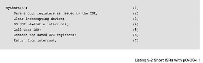
L9-2��1�����������ᵽ�ģ�ISR ͨ�����û��д�ġ�
L9-2(1) As mentioned above, an ISR is
typically written in assembly language. MyShortISR corresponds to the name of
the handler that will handle the interrupting device.
L9-2��2����������� CPU �Ĵ�����
L9-2(2) Here, save sufficient
registers as required to handle the ISR.
L9-2��3������жϱ�־λ����ֹ ISR ����ʱ����ͬ�����жϡ�
L9-2(3) The user may want to clear
the interrupting device to prevent it from generating the same interrupt once
the ISR returns.
L9-2��4�������ﲻҪ���¿����жϡ�
L9-2(4) Do not re-enable interrupts
at this point since another interrupt could make ��C/OS-III calls, forcing a
context switch to a higher-priority task. This means that the above ISR would
complete, but at a much later time.
L9-2��5����Ӧ���ж���Ҫ�IJ����������û�����
L9-2(5) Now take care of the
interrupting device in assembly language or call a C function, if necessary.
L9-2��6������֮�����»ָ�ԭ����� CPU �Ĵ�����
L9-2(6) Once finished, simply restore
the saved CPU registers.
L9-2��7�����ص�ԭ����
L9-2(7) Perform a return from
interrupt to resume the interrupted task.
�� ISR �������������壬��һ�����⡣������ѭ uC/OS-III �Ĺ������� uC/OS-III ��֪�� ISR �з�����ʲô��
Short
ISRs, as described above, should be the exception and not the rule since
��C/OS-III has no way of knowing when these ISRs occur.
Even though an interrupt controller is present in most designs, some
CPUs still vector to a common interrupt handler, and an ISR queries the
interrupt controller to determine the source of the interrupt. At first glance,
this might seem silly since most interrupt controllers are able to force the
CPU to jump directly to the proper interrupt handler. It turns out, however,
that for ��C/OS-III, it is easier to have the interrupt controller vector to a
single ISR handler than to vector to a unique ISR handler for each source.
Listing 9-3 describes the sequence of events to be performed when the interrupt
controller forces the CPU to vector to a single location.
An interrupt occurs;
(1)
The CPU vectors to a common
location;
(2)
The ISR code performs the ��ISR
prologue��
(3)
The C handler performs the
following:
(4)
while (there are still interrupts to
process) {
(5)
Get vector address from interrupt
controller;
Call
interrupt handler;
}
The ��ISR epilogue�� is executed;
(6)
Listing 9-3 Single interrupt vector for all interrupts
|
L9-3(1)
|
An interrupt occurs from any device.
The interrupt controller activates the interrupt pin on the CPU. If there are
other interrupts that occur after the first one, the interrupt controller
will latch them and properly prioritize the interrupts.
|
|
L9-3(2)
|
The CPU vectors to a single interrupt
handler address. In other words, all interrupts are to be handled by this one
interrupt handler.
|
|
L9-3(3)
|
Execute the ��ISR prologue�� code needed by
��C/OS-III. as previously described.
This ensures that all ISRs will be able to
make ��C/OS-III ��post�� calls.
|
|
L9-3(4)
|
Call a ��C/OS-III C handler, which will
continue processing the ISR. This makes the code easier to write (and read).
Notice that interrupts are not re-enabled.
|
|
L9-3(5)
|
The ��C/OS-III C handler then
interrogates the interrupt controller and asks it: ��Who caused the
interrupt?�� The interrupt controller will either respond with a number (1 to
N) or with the address of the interrupt handler for the interrupting device.
Of course, the ��C/OS-III C handler will know how to handle the specific
interrupt controller since the C handler is written specifically for that
controller.
|
If the interrupt controller provides a number between 1 and N, the C handler
simply uses this number as an index into a table (in ROM or RAM) containing the
address of the interrupt service routine servicing the interrupting device. A
RAM table is handy to change interrupt handlers at run-time. For many embedded
systems, however, the table may also reside in ROM.
If the interrupt controller responds with the address of the
interrupt service routine, the C handler only needs to call this function.
In both of the above cases, all interrupt handlers need to be
declared as follows:
void
MyISRHandler (void);
There is one such handler for each possible interrupt source
(obviously, each having a unique name).
The ��while�� loop terminates when there are no other interrupting devices to
service.
L9-3(6) The ��C/OS-III ��ISR epilogue�� is executed to see if it is
necessary to return to the interrupted task, or switch to a more important one.
A couple of interesting points to notice:
�� If another device caused an interrupt before the C handler had a
chance to query the interrupt controller, most likely the interrupt controller
will capture that interrupt. In fact, if that second device happens to be a
higher-priority interrupting device, it will most likely be serviced first, as
the interrupt controller will prioritize the interrupts.
�� The loop will not terminate until all pending interrupts are
serviced. This is similar to allowing nested interrupts, but better, since it
is not necessary to redo the ISR prologue and epilogue.
The disadvantage of this method is that a high priority interrupt
that occurs after the servicing of another interrupt that has already started
must wait for that interrupt to complete before it will be serviced. So, the
latency of any interrupt, regardless of priority, can be as long as it takes to
process the longest interrrupt.
�ж������������е��ж�������ָ���Ӧ�� ISR ��ַ��ISR �еij������û��д�����½� 9-2 ��ʾ������Ȼ�������ᵼ�±�̵ĸ��ӻ���Ȼ�������дֵĴ��붼�Ǵ���һ��
ISR �и��ƺ�����ġ�
If
the interrupt controller vectors directly to the appropriate interrupt handler,
each of the ISRs must be written in assembly language as described in section
9-2 ��Typical ��C/OS-III Interrupt Service Routine (ISR)�� on page 159. This, of
course, slightly complicates the design. However, copy and paste the majority
of the code from one handler to the other and just change what is specific to
the actual device.
����һЩ�û�Ҫ�ı�Ĵ��롣
If
the interrupt controller allows the user to query it for the source of the
interrupt, it may be possible to simulate the mode in which all interrupts
vector to the same location by simply setting all vectors to point to the same
location. Most interrupt controllers that vector to a unique location, however,
do not allow users to query it for the source of the interrupt since, by
definition, having a unique vector for all interrupting devices should not be
necessary.
uC/OS-III
�����ַ��������������жϵ�ʱ�䣻ֱ���ύ���ӳ��ύ��ͨ�� OS_CFH.H �е� OS_CFG_ISR_POST_DEFERRED_EN ��ѡ������Ϊ 0 ʱ��uC/OS-III ʹ��ֱ���ύ������ ������Ϊ 1 ʱ��ʹ���Ƴ��ύ������
����Ӧ��ѡ��һ�ַ�����
��C/OS-III
handles event posting from interrupts using two different methods: Direct and
Deferred Post. The method used in the application is selected by changing the
value of OS_CFG_ISR_POST_DEFERRED_EN in OS_CFG.H (this assumes you have access
to ��C/OS-III��s source code). When set to 0, ��C/OS-III uses the Direct Post
Method and when set to 1, ��C/OS-III uses the Deferred Post Method.
As
far as application code and ISRs are concerned, these two methods are
completely transparent. It is not necessary to change anything except the
configuration value OS_CFG_ISR_POST_DEFERRED_EN to switch between the two
methods. Of course, changing the configuration constant will require
recompiling the product and ��C/OS-III.
Before
explaining why to use one versus the other, let us review their differences.
9-6-1 ֱ���ύ
ͼ 9-2 ��ʾ��ֱ���ύ�����Ĺ��̡�
The
Direct Post Method is used by ��C/OS-II and is replicated in ��C/OS-III. Figure
9-2 shows a task diagram of what takes place in a Direct Post.
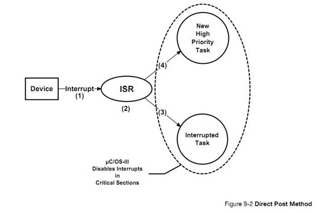
F9-2��1���жϲ���
F9-2(1) A device generates an
interrupt.
F9-2��2���жϷ������ʼִ�С�ͨ���ж��а���������ȴ����¼���
F9-2(2) The Interrupt Service Routine
(ISR) responsible to handle the device executes (assuming interrupts are
enabled). The device interrupt is generally the event a task is waiting for.
The task waiting for this interrupt to occur either has a higher priority than
the interrupted task, or lower (or equal) in priority.
F9-2��3���� ISR ʹ���˵��ڻ����ԭ�������ȼ�������ISR ����ʱ��uC/OS-III ����ԭ���ӱ��жϴ�����ִ�С�
F9-2(3) If the ISR made a lower (or
equal) priority task ready to run then upon completion of the ISR, ��C/OS-III
returns to the interrupted task exactly at the point the interrupt occurred.
F9-2��4���� ISR ʹ���˸���ԭ�������ȼ�������ISR ����������ȡ�uC/OS-III �л��������ȼ�����
F9-2(4) If the ISR made a higher
priority task ready to run, ��C/OS-III will context switch to the new
higher-priority task since the more important task was waiting for this device
interrupt.
F9-2��5����ֱ���ύ�����У�uC/OS-III ���뱣�����ٽ�Σ�ͨ�����жϷ�ʽ����
F9-2(5) In the Direct Post Method,
��C/OS-III must protect critical sections by disabling interrupts as some of
these critical sections can be accessed by ISRs.
Ȼ��������û��������ijЩ uC/OS-III ����ʱ���жϿ��ܱ��رա�������
OS_CFG_ISR_POST_DEFERRED_EN Ϊ 0 ʱ���������ٽ�δ���ʱ uC/OS-III ��ر��жϡ��������жϾͿ��ܲ�����Ӧֱ�� uC/OS-III ���¿��жϡ�
The
above discussion assumed that interrupts were enabled and that the ISR could
respond quickly to the interrupting device. However, if the application code
makes ��C/OS-III service calls (and it will at some point), it is possible that
interrupts would be disabled. When OS_CFG_ISR_POST_DEFERRED_EN is set to 0,
��C/OS-III disables interrupts while accessing critical sections. Thus,
interrupts will not be responded to until ��C/OS-III re-enables interrupts. Of
course, attempts were made to keep interrupt disable times as short as
possible, but there are complex features of ��C/OS-III that disable interrupts
for a longer period than the user would like.
ֱ���ύ������һ����Ҫ�������� uC/OS-III ���жϵ�ʱ�䡣������ױ�ȷ����Ϊ uC/CPU ���ṩ�˲��������ж�ʱ��Ĺ��ܡ���Щ������Ա�ʹ�����ڲ��ԡ�����ʱ����Ӧ�ó������й�����ʱ�䲢��ȡ����CPU_IntDisMeasMaxRaw_cnts����������ľ���ȡ�������ڲ����Ķ�ʱ���ٶȡ�
The
key factor in determining whether to use the Direct Post Method is generally
the ��C/OS-III interrupt disable time. This is fairly easy to determine since
the ��C/CPU files provided with the ��C/OS-III port for the processor used
includes code to measure maximum interrupt disable time. This code can be
enabled (assumes you have the source code) for testing purposes and removed
when ready to deploy the product. The user would typically not want to leave
measurement code in production code to avoid introducing measurement artifacts.
Once instrumented, let the application run for sufficiently long and read the
variable CPU_IntDisMeasMaxRaw_cnts. The resolution (in time) of this variable
depends on the timer used during the measurement.
�ж��ӳ�ʱ�䡢�ж���Ӧʱ�� ���жϻָ�ʱ�䡢�����ӳ�ʱ��ļ���������£�
Determine
the interrupt latency, interrupt response, interrupt recovery, and task latency
by adding the execution times of the code involved for each, as shown below.
�ж��ӳ� = uC/OS-III �������ж�ʱ�䣻
{�ٶ��ж��� uC/OS-III �иս����ٽ��ʱ����}
�ж���Ӧ = �ж��ӳ� + ת�� ISR ʱ�� + ISR ��ǰ��ʱ��
�жϻָ�=�����ж�����+�����ź�������Ϣ������+OSIntExit()+OSIntCtxSw()
�����ӳ� = �ж���Ӧ + �жϻָ� + ��������ʱ��
|
Interrupt Latency =
|
Maximum
interrupt disable time;
|
|
Interrupt Response =
|
Interrupt
latency
+
Vectoring to the interrupt handler
+
ISR prologue;
|
|
Interrupt Recovery
|
=
|
Handling
of the interrupting device
+ Posting a signal or a message
to a task
+
OSIntExit()
+
OSIntCtxSw();
|
|
Task Latency
|
=
|
Interrupt
response
+
Interrupt recovery
+
Time scheduler is locked;
|
uC/OS-III
�� ISR ǰ��ISR ����OSIntExit()��OSIntCtxSw()������ʱ����Ա�������
The execution
times of the ��C/OS-III ISR prologue, ISR epilogue, OSIntExit(), and
OSIntCtxSw(), can be measured independently and should be fairly constant.
���� OS_TS_GET()Ҳ���Բ�����post�������Ĵ���ʱ�䡣
It
should also be easy to measure the execution time of a post call by using
OS_TS_GET().
��ֱ���ύ��ʽ�У�ֻ���ڴ�����ʱ������ʱ�Ż����������������ʱ�������д����Ķ�ʱ������Ļ��������ӳٽ���̡ܶ�uC/OS-III Ҳ���Բ�����������ʱ�䡣
In
the Direct Post Method, the scheduler is locked only when handling timers and
therefore, task latency should be fast if there are not too many timers with
short callbacks expiring at the same time. See Chapter 12, ��Timer Management��
on page 193. ��C/OS-III is also able to measure the amount of time the scheduler
is locked, providing task latency.
9-6-2 �ӳ��ύ��ʽ
�ӳ��ύ��ʽ��ͨ������ OS_CFG_ISR_POST_DEFERRED_ENΪ 1���������˹��жϷ�ʽ���ڴ����ٽ�Ρ�uC/OS-III ��ס������������Ա���������������ٽ�δ��롣�ӳ��ύ��ʽ�У��жϼ���û���رա�Ȼ�����÷�ʽ�е㸴�ӡ���ͼ 9-3 ��ʾ
In
the Deferred Post Method (OS_CFG_ISR_POST_DEFERRED_EN is set to 1), instead of
disabling interrupts to access critical sections, ��C/OS-III locks the
scheduler. This avoids having other tasks access critical sections while
allowing interrupts to be recognized and serviced. In the Deferred Post Method,
interrupts�� are almost never disabled. The Deferred Post Method is, however, a
bit more complex as shown in Figure 9-3.
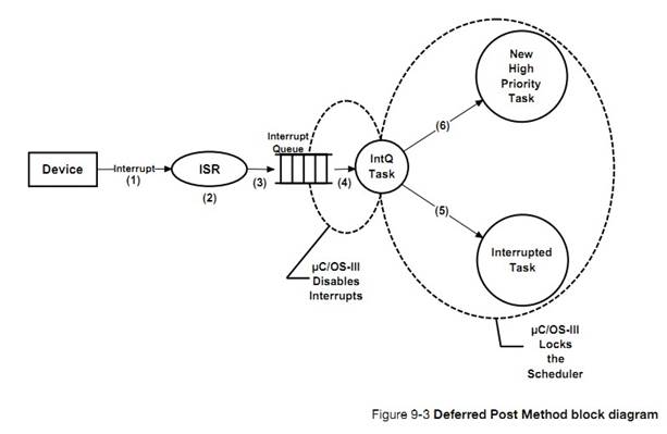
F9-3��1���жϲ���
F9-3(1) A device generates an
interrupt.
F9-3��2��ISR ��ִ�С�
F9-3(2) The ISR responsible for handling
the device executes (assuming interrupts are enabled). The device interrupt is
the event that a task was waiting for. The task waiting for this interrupt to
occur is either higher in priority than the interrupted task, lower, or equal
in priority.
F9-3��3��ISR �е���"post"���������ź�������Ϣ������Ȼ����������ֱ�ӷ����������ȷ��͵��ж϶��С�Ȼ���жϴ������������������� uC/OS-III ���ڲ������Ҿ���������ȼ�(���ȼ�Ϊ 0)��
F9-3(3) The ISR calls one of the post
services to signal or send a message to a task. However, instead of performing
the post operation, the ISR queues the actual post call along with arguments in
a special queue called the Interrupt Queue. The ISR then makes the Interrupt
Queue Handler Task ready to run. This task is internal to ��C/OS-III and is
always the highest priority task (i.e., Priority 0).
F9-3��4��ISR �����uC/OS-III ���л����жϴ������������ж϶�������Ϣ���������ڴˣ����ǹر��жϷ�ֹ�ڴ����ж϶���ʱ��������жϳ����ϡ��������ʹ���жϣ���ס���������ύ��Ϣ����Ϣ���������ύ�ġ���������������������ٽ�εĴ����ˡ�
F9-3(4) At the end of the ISR,
��C/OS-III always context switches to the interrupt queue handler task, which
then extracts the post command from the queue. We disable interrupts to prevent
another interrupt from accessing the interrupt queue while the queue is being
emptied. The task then re-enables interrupts, locks the scheduler, and performs
the post call as if the post was performed at the task level all along. This
effectively manipulates critical sections at the task level.
F9-3��5�����жϴ�����������ж϶���ʱ�����ͻὫ�Լ�ֹͣ����
�¿��������������õ�����ѡ����һ���������С�
F9-3(5) When the interrupt queue
handler task empties the interrupt queue, it makes itself not ready to run and
then calls the scheduler to determine which task must run next. If the original
interrupted task is still the highest priority task, ��C/OS-III will resume that
task.
F9-3��6��������ȼ����ߵ�����ʹ�ܣ�uC/OS-III ���ϻ���������
F9-3(6) If, however, a more important
task was made ready to run because of the post, ��C/OS-III will context switch
to that task.
ִ��һЩ����Ĵ������ڴ����ٽ��ʱ���Ա�����жϡ�����Ĵ���ֻ��������"post"����������Ϣ���ź���������У����Ӷ�������ȡ����ִ�ж�����������л���
All
the extra processing is performed to avoid disabling interrupts during critical
sections of code. The extra processing time only consist of copying the post
call and arguments into the queue, extracting it back out of the queue, and
performing an extra context switch.
������ֱ���ύ��ʽ��
Similar
to the Direct Post Method, it is easy to determine interrupt latency, interrupt
response, interrupt recovery, and task latency, by adding execution times of
the pieces of code involved for each as shown below.
�ж��ӳ� = uC/OS-III �������ж�ʱ�䣻
�ж���Ӧ = �ж��ӳ�+ ת�� ISR ʱ�� + ISR ��ǰ��ʱ��
�жϻָ� = �����ж�����+ �����ź�������Ϣ���ж϶��� + OSIntExit()
+ OSIntCtxSw()�л����ж϶��д�������
�����ӳ� = �ж���Ӧ+ �жϻָ�+ ���ź�������Ϣ�ύ������
+ �������л������� + ��������ʱ��
|
Interrupt Latency =
|
Maximum
interrupt disable time;
|
|
Interrupt Response =
|
Interrupt
latency
+
Vectoring to the interrupt handler
+
ISR prologue;
|
|
Interrupt Recovery =
|
Handling
of the interrupting device
+ Posting a signal or a message
to the Interrupt Queue
|
+ OSIntExit()
+ OSIntCtxSw() to Interrupt Queue Handler Task;
Task Latency = Interrupt
response
+ Interrupt recovery
+ Re-issue the post to the object or task
+ Context switch to task
+ Time scheduler is locked;
��ʵ�ϣ��ӳ��ύ��ʽ�е�"post"������̣ܶ���Ϊ���������"post"
�����ú����IJ������ж϶����С�
The execution
times of the ��C/OS-III ISR prologue, ISR epilogue, OSIntExit(), and
OSIntCtxSw(), can be measured independently and should be constant.
It
should also be easy to measure the execution time of a post call by using
OS_TS_GET(). In fact, the post calls should be short in the Deferred Post
Method because it only involves copying the post call and its arguments into
the interrupt queue.
��ͬ���ǣ��ӳ��ύ��ʽ�й��жϵ�ʱ���Ƿdz��̵ġ�Ȼ���������ӳ�ʱ��䳤��Ϊ uC/OS-III ����ס���������������ٽ�Ρ�
The
difference is that in the Deferred Post Method, interrupts are disabled for a
very short amount of time and thus, the first three metrics should be fast.
However, task latency is higher as ��C/OS-III locks the scheduler to access
critical sections.
��ֱ���ύ��ʽ�У�uC/OS-III �����ٽ��ʱ���жϡ�Ȼ�������ӳ��ύ��ʽ�У�uC/OS-III �����ٽ��ʱ����������
In
the Direct Post Method, ��C/OS-III disables interrupts to access critical
sections. In comparison, while in the Deferred Post Method, ��C/OS-III locks the
scheduler to access the same critical sections.
���ӳ��ύ��ʽ�У������ж϶���ʱ uC/OS-III ��Ҫ���жϡ�Ȼ������ι��ж�ʱ���Ƿdz��̵������൱�̶��ġ�
In
the Deferred Post Method, ��C/OS-III must still disable interrupts to access the
interrupt queue. However, the interrupt disable time is very short and fairly
constant.
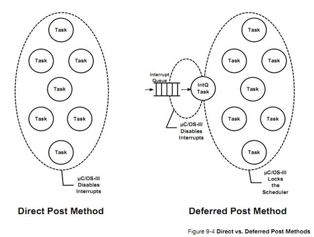
�����Ӧ���й��ж�ʱ���ǹؼ��Եģ���ΪӦ�����зdz�Ƶ�����ж�Դ����Ӧ�ò��ܽ���ֱ���ύ��ʽ�����ϳ��Ĺ��ж�ʱ�䡣�Ƽ�ʹ���ӳ��ύ��ʽ��
If
interrupt disable time is critical in the application because there are very
fast interrupt sources and the interrupt disable time of ��C/OS-III is not
acceptable using the Direct Post Method, use the Deferred Post Method.
Ȼ�����������Ҫʹ�ñ� 9-1 ��һЩ���ܣ���ô�Ϳ������ӳ��ύ��ʽ��
However,
if you are planning on using the features listed in Table 9-1, consider using
the Deferred Post Method, described in the next section.
|
����
|
ԭ��
|
|
������������ͬ���ȼ�
Multiple
tasks at the same priority
|
��
uC/OS-III ��һ����Ҫ���ܣ�����������������ȼ������һ�����ٽ�Ρ�Ȼ�������������������ͬ���ȼ�ʱ���ж���ʱ���С������������в�ͬ���ȼ�ʱ�������ù��жϷ�����
Although
this is an important feature of ��C/OS-III, multiple
tasks at the same priority create longer critical sections. However, if there
are only a few tasks at the same priority, interrupt latency will be
relatively small. If the user does not create multiple tasks at the same
priority, the Direct Post Method is recommended.
|
|
�¼���־������½�
14��ͬ����
Event
Flags
Chapter
14, Synchronization�� on page 251
|
����������ȴ���ͬ���¼���������Щ�ȴ��¼���������Ҫ�ܶദ��ʱ�䣬��ζ�Ż�������ٽ�Ρ�������ٵ������ڵȴ��¼����ٽ�λ�̣ܶ���ô����ʹ�ù��жϵķ���������
If
multiple tasks are waiting on different events, going through all of the tasks
waiting for events requires a fair amount of processing time, which means
longer critical sections.
If
only a few tasks (approximately one to five) are waiting on an event flag
group, the critical section will be short enough to use the Direct Post Method.
|
|
����ȴ��������
����½� 16
Pend
on multiple objects
Chapter
16,��Pending On Multiple Objects�� on page 313
|
������������
uC/OS-III �ṩ�ĺܸ��ӵĹ��ܣ�����Ҫ�ܳ����ٽ�Ρ�����������Ƽ�ʹ�ùص������ķ��������������٣����ж�Ҳ�ǿ��Եġ�
Pending
on multiple objects is probably the most complex feature provided by ��C/OS-III and requires interrupts to be disabled for fairly long
periods of time when using the Direct Post Method.
If
pending on multiple objects, the Deferred Post Method is highly recommended.
If
the application does not use this feature, the user may select the Direct
Post Method.
|
|
�㲥��Ϣ�����¼
A �е�
Broadcast
on Post calls
OSSemPost()��
OSQPost()
|
uC/OS-III �ڴ����㲥��Ϣʱͨ���ص����������ٽ�Ρ�����ʹ�ù㲥���ܵ�ʱ��������ù��жϷ���
��C/OS-III disables interrupts while processing a post to multiple
tasks in a broadcast.If not using the broadcast option, use the Direct Post
Method.Note that broadcasts only apply to semaphores and message queues.
|
�� 9-1 ��ʹ��ֱ���ύ��ʽʱ����ʹ����Щ����
uC/OS-III
��Ҫһ�����ṩ������ʱ���ʱ��Դ������ϵͳʱ����
��C/OS-III-based
systems generally require the presence of a periodic time source called the
clock tick or system tick.
Ӳ����ʱ�����Ա�����Ϊÿ����� 10 �� 1000Hz ���ж��ṩϵͳʱ����Ҳ���Դӽ������л�� 50Hz �� 60Hz ��ʱ��Դ����ʵ�ϣ�Ҳ���Դӽ������л�� 100Hz �� 120Hz �Ĺ������Ϊʱ����
A
hardware timer configured to generate an interrupt at a rate between 10 and
1000 Hz provides the clock tick. A tick source may also be obtained by
generating an interrupt from an AC power line (typically 50 or 60 Hz). In fact,
one can easily derive 100 or 120 Hz by detecting zero crossings of the power
line.
ʱ�����Կ�����ϵͳ���������������ʾ�����ʱ��Դ��Ȼ����ʱ������Խ�죬ϵͳ�Ķ���֧����Խ��
The
clock tick interrupt can be viewed as the system��s heartbeat. The rate is
application specific and depends on the desired resolution of this time source.
However, the faster the tick rate, the higher the overhead imposed on the
system.
The
clock tick interrupt allows ��C/OS-III to delay tasks for an integral number of
clock ticks and provide timeouts when tasks are waiting for events to occur.
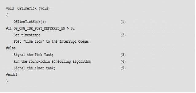
ʱ���жϳ��������� OSTimeTick()��OSTimeTick()��α�������б� 9-4 ��ʾ��
The
clock tick interrupt must call OSTimeTick(). The pseudocode for OSTimeTick() is
shown in Listing 9-4.
L9-4��1��ʱ���жϳ������ȵ���һ�� hook ������OSTimeTickHook()����������ʱ���жϳ���ʱ�û���չһЩ������Hook ������ʱ���жϷ���ʱ���ȱ����õģ���������һЩ������Ԫ�ء����ȡ���������豻�����Լ�⣩������ PWM �Ĵ����ȵȡ�
L9-4(1) The time tick ISR starts by
calling a hook function, OSTimeTickHook(). The hook function allows the
implementer of the ��C/OS-III port to perform additional processing when a tick
interrupt occurs. In turn, the tick hook can call a user-defined tick hook if
its corresponding pointer, OS_AppTimeTickHookPtr, is non-NULL. The reason the
hook is called first is to give the application immediate access to this
periodic time source. This can be useful to read sensors at a regular interval
(not as subject to jitter), update Pulse Width Modulation (PWM) registers, and
more.
L9-4��2����� uC/OS-III ������Ϊ�ӳ��ύ��ʽ��uC/OS-III ��ȡ��ǰʱ��������õ��жϴ������С�Ȼ���ж϶��д����������ź�����ʱ������
L9-4(2) If ��C/OS-III is configured
for the Deferred Post Method, ��C/OS-III reads the current timestamp and defers
the call to signal the tick task by placing an appropriate entry in the
interrupt queue. The tick task will thus be signaled by the Interrupt Queue
Handler Task.
L9-4��3����� uC/OS-III ������Ϊֱ���ύ��ʽ��ʱ�� ISR ֱ�ӷ����ź�����ʱ������
L9-4(3) If ��C/OS-III is configured
for the Direct Post Method, ��C/OS-III signals the tick task so that it can
process the time delays and timeouts.
L9-4��4��ʹ��ѭ����ת�㷨����Ƿ�ǰ�����Ƿ�������
L9-4(4) ��C/OS-III runs the
round-robin scheduling algorithm to determine whether the time slot for the
current task has expired.
L9-4��5����Ƕ�ʱ������ʱ������Ҳ��ʱ�������ʱ����Ϊ����
L9-4(5) The tick task is also used as
the time base for the timers (see Chapter 13, ��Resource Management�� on page
209).
uC/OS-III
������ϵͳʱ�����ձ����⡣��ʵ�ϣ��ܶ����Ӧ����û��ϵͳʱ������Ϊ��������������ά��ʱ��Դ�����仰˵������������ά��ʱ��Դ�Dz������ġ���Ϊ uC/OS-III ��һ������ռʽ�ںˣ�һ���¼����Ի��ѽ������ģʽ�������������������¼�����û��ʱ����ζ���û������ٶ����������ʱ��ʱ���á��û����з����IJ�Ʒʱ���Կ���������ԡ�
A
common misconception is that a system tick is always needed with ��C/OS-III. In
fact, many low-power applications may not implement the system tick because of
the power required to maintain the tick list. In other words, it is not
reasonable to continuously power down and power up the product just to maintain
the system tick. Since ��C/OS-III is a preemptive kernel, an event other than a
tick interrupt can wake up a system placed in low power mode by either a
keystroke from a keypad or other means. Not having a system tick means that the
user is not allowed to use time delays and timeouts on system calls. This is a
decision required to be made by the designer of the low-power product.
uC/OS-III
�ṩ�����жϵķ���ISR Ӧ��Խ��Խ�ã������ź�������Ϣ�������ø�����ʵ�ָ��ж�����Ĵֲ������������ò�����������ɡ�
��C/OS-III
provides services to manage interrupts. An ISR should be short in length, and
signal or send a message to a task, which is responsible for servicing the
interrupting device.
ISR
Ҳ���Բ������ź�������Ϣ������ISR �Լ�������Ӧ��������
ISR Խ��Խ�á�
ISRs
that are short and do not need to signal or send a message to a task, are not
required to do so.
uC/OS-III
�����������ж�ʱָ��ͬһ�� ISR������ָ����Ե�ISR��
��C/OS-III
supports processors that vector to a single ISR for all interrupting devices,
or to a unique ISR for each device.
uC/OS-III
֧�����ַ�ʽ:ֱ���ύ��ʽ���ӳ��ύ��ʽ��ֱ���ύ��ʽ��Ҫ���жϱ����ٽ�Ρ��ӳ��ύ��ʽ��Ҫ�ص����������ٽ�Ρ�
��C/OS-III
supports two methods: Direct and Deferred Post. The Direct Post Method assumes
that ��C/OS-III critical sections are protected by disabling interrupts. The
Deferred Post Method locks the scheduler when ��C/OS-III accesses critical
sections of code.
uC/OS-III
��Ҫʱ��Դ�������������ʱ�ͳ�ʱ���ܡ�
��C/OS-III
assumes the presence of a periodic time source for applications requiring time
delays and timeouts on certain services.
10���������
������ȴ��ź�����mutex���¼���־�顢��Ϣ����ʱ��������ᱻ���������С�
A task
is placed in a Pend List (also called a Wait List) when it is waiting on a
semaphore to be signaled, a mutual exclusion semaphore to be released, an event
flag group to be posted, or a message queue to be posted.
|
�μ�
|
�������
|
�ں˶���
|
|
�½� 13����Դ������
|
�ź�����mutex
|
OS_SEM��OS_MUTEX
|
|
�½� 14��ͬ����
|
�ź������¼���־��
|
OS_SEM��OS_FLAG_GRP
|
|
�½� 15����Ϣ�ύ��
|
��Ϣ����
|
OS_Q
|
�� 10-1 ����������ں˶���
������������ھ������У���������зŵ��ǵȴ��ں˶�����������⣬�����ڹ���������Ǹ������ȼ�����ġ������ȼ��������ڶ��е�ͷ���������ȼ��������ڶ��е�β����
A
pend list is similar to the Ready List, except that instead of keeping track of
tasks that are ready-to-run, the pend list keeps track of tasks waiting for an
object to be posted. In addition, the pend list is sorted by priority; the
highest priority task waiting on the object is placed at the head of the list,
and the lowest priority task waiting on the object is placed at the end of the
list.
���������һ�� OS_PEND_LIST ���͵����ݽṹ�������������������ݣ���ͼ 10-1
A
pend list is a data structure of type OS_PEND_LIST, which consists of three
fields as shown in Figure 10-1.
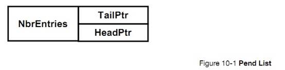
.NbrEntries
����������������
.NbrEntries
Contains the current number of entries in the pend list. Each entry in the pend
list points to a task that is waiting for the kernel object to be posted.
.TailPtr
ָ����е�β����������ȼ������� .HeadPtr ָ����е��ײ���������ȼ�������
.TailPtr Is a pointer to the
last task in the list (i.e., the lowest priority task). .HeadPtr Is a pointer to
the first task in the list (i.e., the highest priority task).
ͼ 10-2 ��ʾ��ÿ���ں˶����еİ�����������ͬ�IJ��֣����ǰ���������������Ϊ
OS_PEND_OBJ��ע����ǣ���һ�����֡�Type�� ������������ں˶�������ͣ��ź�����mutex���¼�����顢��Ϣ���С�
Figure
10-2 indicates that each kernel object using a pend list contains the same
three fields at the beginning of the kernel object that we called an
OS_PEND_OBJ. Notice that the first field is always a ��Type�� which allows
��C/OS-III to know if the kernel object is a semaphore, a mutual exclusion semaphore,
an event flag group, or a message queue object.
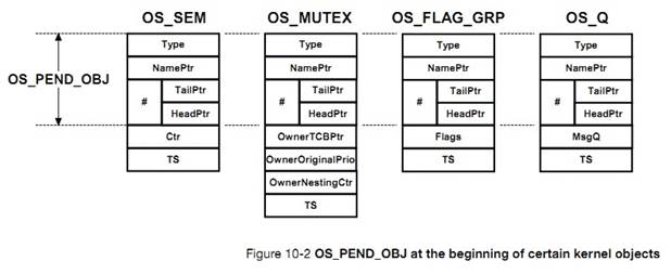
�� 10-2 ��ʾ�˵��ں˶�����ʱ"Type"���ֱ����õ�ֵ������ʱ���Է����û�ʶ���ں˶�������͡�
Table
10-2 shows that the ��Type�� field of each of the above objects is initialized to
contain four ASCII characters when the respective object is created. This
allows the user to identify these objects when performing a memory dump using a
debugger.
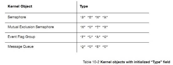
��ʵ�ϣ���������в���ָ������� OS_TCB ������ָ�� OS_PEND_DATA����ͼ 10-3 ��ʾ����������������ʱ��OS_PEND_DATA �ṹ�屻��̬�ط��䵽������Ķ�ջ�С�����ζ�������ջ�������㹻�Ŀռ����ڴ洢����ṹ�塣
A
pend list does not actually point to a task��s OS_TCB, but instead points to
OS_PEND_DATA objects as shown in Figure 10-3. Also, an OS_PEND_DATA structure
is allocated dynamically on the current task��s stack when a task is placed on a
pend list. This implies that a task stack needs to be able to allocate storage
for this data structure.
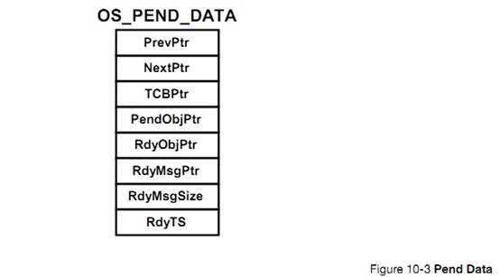
.PrevPtr
��ָ�����ڶ����еȴ��ĸ����ȼ���ͬ�����ȼ�������
.PrevPtr Is a pointer to an
OS_PEND_DATA entry in the pend list. This pointer points to a higher or equal
priority task waiting on the kernel object.
.NextPtr
��ָ�����ڶ����еȴ��ĵ����ȼ�������
.NextPtr Is a pointer to an OS_PEND_DATA
entry in the pend list. This pointer points to a lower or equal priority task
waiting on the kernel object.
.TCBPtr
ָ�������� OS_TCB��
.TCBPtr Is a pointer to the OS_TCB of the
task waiting on the pend list.
.PendObjPtr
ָ���������ȴ����ں˶����仰˵�����ָ�����ָ�� OS_SEM��OS_MUTEX��OS_FLAG_GRP��OS_Q�����ں˶����ж���һ����ͬ�Ľṹ�� OS_PEND_OBJ��
.PendObjPtr Is a pointer to the kernel object
that the task is pending on. In other words, this pointer can point to an
OS_SEM, OS_MUTEX, OS_FLAG_GRP or OS_Q by using an OS_PEND_OBJ as the common
data structure.
.RdyObjPtr
�������ȴ�����ں˶���ָ��ָ������������б�ǰ�Ѿ����ύ���ں˶�������½� 16��������������
.RdyObjPtr Is a pointer to the kernel
object that is ready if the task actually waits for multiple kernel objects.
See Chapter 16, ��Pending On Multiple Objects�� on page 313 for more on this.
.RdyMsgPtr
�������ȴ�����ں˶���ָ��ָ������������б����ύ���ں˶�������½� 16��������������
.RdyMsgPtr Is a pointer to the message posted
through OSQPost() if the task is pending on multiple kernel objects. Again, see
Chapter 16, ��Pending On Multiple Objects�� on page 313.
.RdyTS
���洢���ں˶����ύʱ��ʱ���������ȴ�����ں˶���ʱ���õ����������������½� 16��������������
.RdyTS Is a timestamp of when
the kernel object was posted. This is used when a task pends on multiple kernel
objects as described in Chapter 16, ��Pending On Multiple Objects�� on page 313.
ͼ 10-4 չʾ�˵�������������ʱ��OS_PEND_DATA �ṹ��֮�������ϵ�ġ���ͼ�ٶ���������ȴ�ͬһ���ź�����
Figure
10-4 exhibits how all data structures connect to each other when tasks are
inserted in a pend list. This drawing assumes that there are two tasks waiting
on a semaphore.
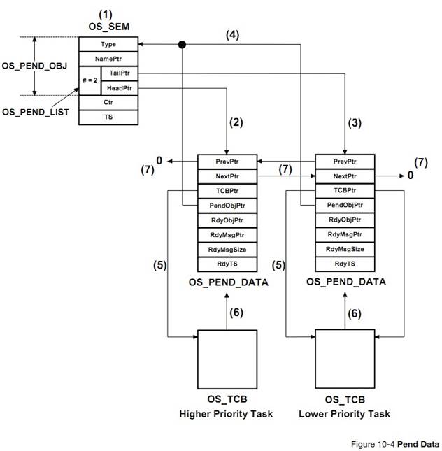
F10-4
�� 1 ���ṹ�� OS_SEM �а�����һ�� OS_PEND_OBJ ��OS_PEND_OBJ �а����� OS_PEND_LIST������.NbrEntries ֵΪ 2��ʾ�������������ڵȴ����ź�����
F10-4(1) The OS_SEM data type contains an
OS_PEND_OBJ, which in turn contains an OS_PEND_LIST. The .NbrEntries field in
the pend list indicates that there are two tasks waiting on the semaphore.
F10-4��2��.HeadPtr ָ������ȼ�����Ľṹ�� OS_PEND_DATA��
F10-4(2) The .HeadPtr field of the pend list
points to the OS_PEND_DATA structure associated with the highest priority task
waiting on the semaphore.
F10-4��3��.TailPtr ָ������ȼ�����Ľṹ�� OS_PEND_DATA��
F10-4(3) The .TailPtr field of the pend list
points to the OS_PEND_DATA structure associated with the lowest priority task
waiting on the semaphore.
F10-4��4������������Ľṹ�� OS_PEND_DATA �зֱ�ͨ��ָ�� PendObjPtr ָ�� OS_SEM �ṹ�塣��ָ����Ϊ�Լ�ָ����� OS_PEND_OBJ{Ҳ���Ǹ�ָ������ OS_PEND_OBJ ���Ͷ����}��ͨ����� OS_PEND_OBJ �е�.Type �Ϳ���֪�����ں˶������ź�����
F10-4(4) Both OS_PEND_DATA structures in turn
point back to the OS_SEM data structure. The pointers think they are pointing
to an OS_PEND_OBJ. We know that the OS_PEND_OBJ is a semaphore by examining the
.Type field of the OS_PEND_OBJ.
F10-4��5��ÿ�� OS_PEND_DATA �ṹ��ֱ�ָ����Ե� OS_TCB�����仰˵����������֪���ĸ������ڵȴ�����ź�����
F10-4(5) Each OS_PEND_DATA structure points to its
respective OS_TCB. In other words, we know which task is pending on the
semaphore.
F10-4��6��ÿ������ָ��ָ�� OS_PEND_DATA �ṹ�塣
F10-4(6) Each task points back to the OS_PEND_DATA
structure.
F10-4��7�����OS_PEND_DATA �ṹ����֯��һ��˫���б��� uC/OS-III �Ϳ��Է�������ӻ��Ƴ��б��еļ�¼��
F10-4(7) Finally, the OS_PEND_DATA structure forms
a doubly linked list so that the ��C/OS-III can easily add or remove entries in
this list.
�� 10-3 ��ʾ�� uC/OS-III ����ά��������еĺ�������Щ�������� uC/OS-III ���ڲ������������� OS_CORE.C �У����û����ܵ������ǡ�
Although
this may seem complex, the reasoning will become apparent in Chapter 16,
��Pending On Multiple Objects�� on page 313. For now, assume all of the links are
necessary.
Table
10-3 shows the functions that ��C/OS-III uses to manipulate entries in a pend
list. These functions are internal to ��C/OS-III and the application code must
never call them.
The
code is found in OS_CORE.C.
|
����
|
����
|
|
OS_PendListChangePrio()
|
�ı��������е���������ȼ�
Change
the priority of a task in a pend list
|
|
OS_PendListInit()
|
��ʼ���������
Initialize
a pend list
|
|
OS_PendListInsertHead()
|
����һ��
OS_PEND_DATA ������
Insert
an OS_PEND_DATA at the head of the pend list
|
|
OS_PendListInsertPrio()
|
�� �� �� �� �� �� �� һ ��OS_PEND_DATA������
Insert
an OS_PEND_DATA in priority order in the pend list
|
|
OS_PendListRemove()
|
�������Ƴ����
OS_PEND_DATA
Remove
multiple OS_PEND_DATA from the pend list
|
|
OS_PendListRemove1()
|
�������Ƴ�һ��
OS_PEND_DATA
Remove
single OS_PEND_DATA from the pend list
|
�� 10-3 ���������غ���
uC/OS-III
���ȴ��ź�����mutex���¼���־�顢��Ϣ���е�����洢����������С�
��C/OS-III
keeps track of tasks waiting for semaphores, mutual exclusion semaphores, event
flag groups and message queues using pend lists.
��������а������ݽṹ OS_PEND_LIST������������һ������OS_PEND_OBJ �����ݽṹ��������ֱ�����ӵ���������У�����ͨ������ OS_PEND_DATA �����ݽṹ��Ϊý�顣���ý�����������������з��䵽�����ջ�ġ�
A
pend list consists of a data structure of type OS_PEND_LIST. The pend list is
further encapsulated into another data type called an OS_PEND_OBJ.
�û����벻�ܷ��ʹ�����У�������� uC/OS-III �ṩ�ĺ�����
Tasks
are not directly linked to the pend list but instead are linked through an
intermediate data structure called an OS_PEND_DATA which is allocated on the
stack of the task waiting on the kernel object.
Application
code must not access pend lists, since these are internal to ��C/OS-III.
11��ʱ�����
uC/OS-III
Ϊ�û��ṩ����ʱ�������صķ���
��C/OS-III
provides time-related services to the application programmer.
�ڵ� 9 �¡��жϹ������У��� uC/OS-III �����������ṩʱ���жϵ��ж�Դ�����ж�Դ�ṩ 10Hz �� 1000Hz ֮����жϣ������� OS_CFG_APP.H �е� OS_CFG_TICK_RATE_HZ Ϊ�ж�Դ�ṩ��Ƶ�ʣ���Ȼ����Ƶ��Խ�ߣ�CPU ��������ľ�Խ�ࡣ
In
Chapter 9, ��Interrupt Management�� on page 157, it was established that
��C/OS-III generally requires (as do most kernels) that the user provide a
periodic interrupt to keep track of time delays and timeouts. This periodic
time source is called a clock tick and should occur between 10 and 1000 times per
second, or Hertz (see OS_CFG_TICK_RATE_HZ in OS_CFG_APP.H). The actual
frequency of the clock tick depends on the desired tick resolution of the
application. However, the higher the frequency of the ticker, the higher the
overhead.
uC/OS-III
�ṩ��һЩ��ʱ����صĺ������ 11-1,��Щ������OS_TIME.C
��
��C/OS-III
provides a number of services to manage time as summarized in Table 11-1, and
the code is found in OS_TIME.C.
|
������
|
����
|
|
OSTimeDly()
|
��ʱִ������ n ��ʱ��
|
|
OSTimeDlyHMSM()
|
��ʱִ������ HH:MM:SS.mmm
|
|
OSTimeDlyResume()
|
�ָ�������ʱ״̬������
|
|
OSTimeGet()
|
��õ�ǰ��ʱ������ֵ
|
|
OSTimeGet()
|
���õ�ǰ��ʱ������ֵ
|
|
OSTimeTick()
|
���ڱ�ǣ���ʾ������һ��ʱ���ж�
|
�� 11-1 ʱ�������ص� API �ܽ�
�����¼ A��uC/OS-III �� API �ο��ֲᡱ��
The application
programmer should refer to Appendix A, ����C/OS-III API Reference Manual�� on page
375 for a detailed description of these services.
����������������ͻᱻ����ֱ�������������������������ģʽ�������ʱģʽ����������ʱģʽ�����Զ�ʱģʽ��
A
task calls this function to suspend execution until some time expires. The
calling function will not execute until the specified time expires. This
function allows three modes: relative, periodic and absolute.
�б� 11-1 ��ʾ�� OSTimeDly()�����ģʽ��
Listing
11-1 shows how to use OSTimeDly() in relative mode.
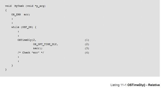
L11-1��1����һ���������������ʱʱ���������ʱ�����ʱ�����Ϊ1000Hz�������ÿ��ִ�ж��ᱻ��ʱ��Լ 2 ���롣Ȼ���������Ǿ�ȷ����ʱ 2 ��ʱ������Ϊ��������Ǽ��ʱ���жϷ����Ĵ������������ʱֵ�Ƿ���ͬ���ж��Ƿ�ʱ�ġ�Ҳ����˵����������ʱ���жϽ�Ҫ����ʱ��������ôʵ�ʵ���ʱʱ������ 1 ��ʱ����
L11-1(1) The first argument specifies the amount
of time delay (in number of ticks) from when the function is called. For
example if the tick rate (OS_CFG_TICK_RATE_HZ in OS_CFG_APP.H) is set to 1000
Hz, the user is asking to suspend the current task for approximately 2
milliseconds. However, the value is not accurate since the count starts from
the next tick which could occur almost immediately. This will be explained
shortly.
L11-1��2������Ϊ OS_OPT_TIME_DLY �����û�ѡ��������ʱģʽ��
L11-1(2) Specifying OS_OPT_TIME_DLY indicates that
the user wants to use ��relative�� mode.
L11-1��3�������� uC/OS-III ����һ����������Żᱻ���ء������еIJ���������Чʱ�᷵�� OS_ERR_NONE��
L11-1(3) As with most ��C/OS-III services an error
return value will be returned. The example should return OS_ERR_NONE as the
arguments are all valid. Refer to Chapter 11, ��Time Management�� on page 183 for
a list of possible error codes.
L11-1��4�������ز�Ϊ OS_ERR_NONE ʱ��OSTimeDly()������ִ����ʱ������
������������ʱʱ�䲻�Ǿ�ȷ�ġ����ͼ 11-1
L11-1(4) Always check the error code returned by
��C/OS-III. If ��err�� does not contain OS_ERR_NONE, OSTimeDly() did not perform
the intended work. For example, another task could remove the time delay
suspension by calling OSTimeDlyResume() and when MyTask() returns, it would not
have returned because the time had expired.
As
mentioned above, the delay is not accurate. Refer to Figure 11-1 and its
description below to understand why.
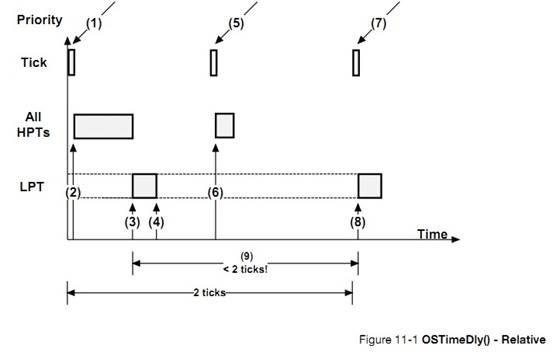
HPT:
�����ȼ�����LPT �����ȼ�����
F11-1��1��ʱ���жϲ���������ʱ�� ISR��
F11-1(1) We get a tick interrupt and
��C/OS-III services the ISR.
F11-1��2��ISR �������л��������ȼ��������ִ��ʱ���Dz���Ԥ��ġ�
F11-1(2) At the end of the ISR, all Higher
Priority Tasks (HPTs) execute. The execution time of HPTs is unknown and can
vary.
F11-1��3���������ȼ�����ִ����Ϻ�uC/OS-III ת����Ҫ����OSTimeDly()������
F11-1(3) Once all HPTs have executed,
��C/OS-III runs the task that has called OSTimeDly() as shown above. For the
sake of discussion, it is assumed that this task is a lower priority task
(LPT).
F11-1��4��������� OSTimeDly()��������Ϊ�ȴ�����ʱ������ʱ�� uC/OS-III �Ὣ����������ʱ�����С��ȴ�����ʱ����ռ��CPU ʱ�䡣
F11-1(4) The task calls OSTimeDly() and
specifies to delay for two ticks in ��relative�� mode. At this point, ��C/OS-III
places the current task in the tick list where it will wait for two ticks to
expire. The delayed task consumes zero CPU time while waiting for the time to
expire.
F11-1��5����һ��ʱ���жϲ��������и����ȼ�������ȴ��˴�ʱ���ж�ʱ�������ȼ�����ᱻִ�С�
F11-1(5) The next tick occurs. If there are
HPTs waiting for this particular tick, ��C/OS-III will schedule them to run at
the end of the ISR.
F11-1��6��ִ�и����ȼ�����
F11-1(6) The HPTs execute.
F11-1��7������һ��ʱ���жϲ��������и����ȼ�������ȴ��˴�ʱ���ж�ʱ�������ȼ�����ᱻִ�С�
F11-1(7) The next tick interrupt occurs.
This is the tick that the LPT was waiting for and will now be made ready to run
by ��C/OS-III.
F11-1��8����Ϊ�˿�û�и����ȼ����жϾ�����uC/OS-III �������л��������ȼ�����Ҳ���ǵ����� OSTimeDly()������
F11-1(8) Since there are no HPTs to execute
on this tick, ��C/OS-III switches to the LPT.
F11-1��9��ʱ���жϺ���Ϊ�����ȼ�������Ҫ��ִ�У����Ը��������ʱʱ�䲻���Ǿ�ȷ�� 2 ��ʱ����
F11-1(9) Given the execution time of the
HPTs, the time delay is not exactly two ticks, as requested.
��Ҫ���ǵ��ǣ�������� OSTimeDly()��ʱ 2 ��ʱ��ʱ������һ��ʱ���жϻ�Ѹ�ٵز���������ͼ������������£�Ҫ��ʱ 2 ��ʱ��ʱ������Ҫ������ʱ 3 ��ʱ����
In
fact, it is virtually impossible to obtain a delay of exactly the desired
number of ticks. One might ask for a delay of two ticks, but the very next tick
could occur almost immediately after calling OSTimeDly()! Just imagine what
might happen if all HPTs took longer to execute and pushed (3) and (4) further
to the right. In this case, the delay would actually appear as one tick instead
of two.
����������Ϊ�� OT_OPT_TIME_PERIDSIC ʱ��OSTimeDly()������Ϊ��������ʱģʽ����������ƥ��ֵ�����������ѵ����ڡ���ͼ 11-2 ��ʾ����ƥ�� ֵ �� �� OSTickCtr ʱ�������� ��
OSTimeDly()
can also be called with the OS_OPT_TIME_PERIODIC option as shown in Listing
11-2. This option allows delaying the task until the tick counter reaches a
certain periodic match value and thus ensures that the spacing in time is
always the same as it is not subject to CPU load variations.
��C/OS-III determines the ��match value�� of OSTickCtr to determine when the task will need to wake up based
on the desired period. This is shown in Figure 11-2. ��C/OS-III
checks to ensure that if the match is computed such that it represents a value
that has already gone by then, the delay will be zero.
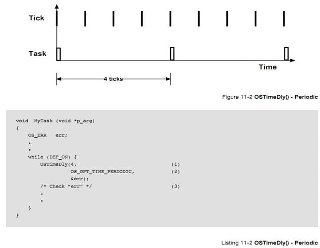
L11-2��1����һ����������������ִ�е����ڣ����ϱ�����Ϊ 4 ��ʱ����
L11-2(1) The first argument specifies the period
for the task to execute, specifically every four ticks. Of course, if the task
is a low-priority task, ��C/OS-III only schedules and runs the task based on its
priority relative to what else needs to be executed.
L11-2��2���ڶ������� OS_OPT_TIME_PERIODIC ������������Ϊ���������С�
L11-2(2) Specifying OS_OPT_TIME_PERIODIC indicates
that the task is to be ready to run when the tick counter reaches the desired
period from the previous call.
L11-2��3����� uC/OS-III ���صĴ�����š�
L11-2(3) You should always check the error code
returned by ��C/OS-III.
�����ʱģʽ����������ʱģʽ�������Dz�һ���ģ������������Ƶġ����Ƕ����ܶ�ʧһ��ʱ�����и����ȼ�����ִ�кܳ�ʱ��ʱ��
Relative
and Periodic modes might not look different, but they are. In Relative mode, it
is possible to miss one of the ticks when the system is heavily loaded, missing
a tick or more on occasion. In Periodic mode, the task may still execute later,
but it will always be synchronized to the desired number of ticks. In fact,
Periodic mode is the preferred mode to use to implement a time-of-day clock.
��������ʹ�þ���ʱ��ģʽ������ʱ��Ҫ��ܸߵ��������磬�����Ʒ���ϵ�ĵ� 10 ��ر� LED������������£������Ҫ����Ϊ����ʱ��ģʽ OS_OPT_TIME_MATCH������ OSTickCtr ֵΪ10 ����ʱ��Ƶ�ʡ�
Finally,
you can use the absolute mode to perform a specific action at a fixed time
after power up. For example, turn off a light 10 seconds after the product
powers up. In this case, you would specify OS_OPT_TIME_MATCH while ��dly��
actually corresponds to the desired value of OSTickCtr you want to reach.
�ܽ�� OSTickCtr ������ֵʱƥ��ʱ�����ѣ�
To
summarize, the task will wake up when OSTickCtr reaches the following value:
|
ѡ��
|
����ʱ��ƥ��ֵ
|
|
OS_OPT_TIME_DLY
|
OSTickCtr + dly
|
|
OS_OPT_TIME_PERIODIC
|
OSTCBCurPtr->TickCtrPrev+dly
|
|
OS_OPT_TIME_MATCH
|
dly
|
dly
Ϊ���������ĵ�һ������
������Ե����������Ϊ����������ʱ��������������Ѻá����û����ر�ģ���������ΪСʱ�����ӣ��룬���루HMSM �ɴ��ĸ�Ӣ������ĸ���������������ֻ�������ʱģʽ�����С�
A task
may call this function to suspend execution until some time expires by
specifying the length of time in a more user-friendly way. Specifically,
specify the delay in hours, minutes, seconds, and milliseconds (thus the HMSM).
This function only works in ��Relative�� mode.
�б� L11-3 ������ OSTimeDlyHMSM()��
Listing
11-3 indicates how to use OSTimeDlyHMSM().
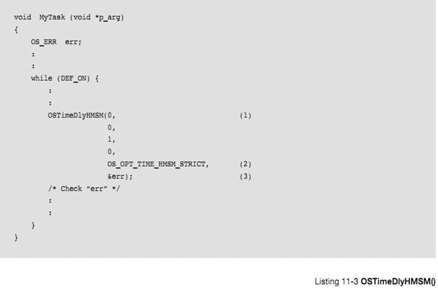
L11-3��1�����ĸ�������������ʱ��ʱ��(�ֱ��ӦΪʱ���֡��롢����)������������У���������ʱ 1 �롣��ʱ�ķֱ��ʾ�����ʱ��Ƶ�ʡ����磬���ʱ��Ƶ��Ϊ 1000Hz ��ô��ʱ�ķֱ���Ϊ 1 ���롣���ʱ����Ƶ��Ϊ 100Hz ��ô��ʱ�ķֱ���Ϊ 10 ���롣ͬ���ģ���ʱʱ�䲻��ܾ�ȷ��
L11-3(1) The first four arguments specify the
amount of time delay (in hours, minutes, seconds, and milliseconds) from this
point in time. In the above example, the task should delay by 1 second. The
resolution greatly depends on the tick rate. For example, if the tick rate
(OS_CFG_TICK_RATE_HZ in OS_CFG_APP.H) is set to 1000 Hz there is technically a
resolution of 1 millisecond. If the tick rate is 100 Hz then the delay of the
current task is in increments of 10 milliseconds. Again, given the relative
nature of this call, the actual delay may not be accurate.
L11-3��2������ OS_OPT_TIME_HMSM_STRICT ����⺯���IJ����Ƿ������Сʱ�ķ�Χ�� 0 �� 99���ֵķ�Χ�� 0 �� 59����ķ�Χ�� 0 �� 59������ķ�Χ�� 0 �� 999��
L11-3(2) Specifying OS_OPT_TIME_HMSM_STRICT
verifies that the user strictly passes valid values for hours, minutes, seconds
and milliseconds. Valid hours are 0 to 99, valid minutes are 0 to 59, valid
seconds are 0 to 59, and valid milliseconds are 0 to 999.
�������Ϊ OS_OPT_TIME_HMSM_NON_STRICT����������ܲ����ķ�Χ���Сʱ�ķ�Χ�� 0 �� 999���ֵķ�Χ�� 0 �� 9999����ķ�Χ�� 0 ��
65535������ķ�Χ�� 0 �� 4294967295��
If
specifying OS_OPT_TIME_HMSM_NON_STRICT, the function will accept nearly any
value for hours (between 0 to 999), minutes (from 0 to 9999), seconds (any
value, up to 65,535), and milliseconds (any value, up to 4,294,967,295).
OSTimeDlyHMSM(203, 101, 69, 10000) may be accepted. Whether or not this makes
sense is a different story.
����Сʱ��ΧΪ 0 �� 999 ��ԭ���ǣ�һ������
32 λ������¼ʱ��ֵ�ġ����ʱ����Ƶ��Ϊ 1000Hz����ô����ܼ��� 4294967 �룬��Լ 1193 Сʱ��������� 999 СʱΪ���ޡ�
The
reason hours is limited to 999 is that time delays typically use 32-bit values
to keep track of ticks. If the tick rate is set at 1000 Hz then, it is possible
to only track 4,294,967 seconds, which corresponds to 1,193 hours, and
therefore 999 is a reasonable limit.
L11-3��3�������� uC/OS-III ����һ������һ��������š�
L11-3(3)
As with most ��C/OS-III services the user will receive an error return value.
The example should return OS_ERR_NONE since the arguments are all valid. Refer
to Appendix A, ����C/OS-III API Reference Manual�� on page 375 for a list of
possible error codes.
��Ȼ uC/OS-III ���������кܳ�����ʱʱ�䣬�����Ƽ�����ʱ����ʱ����Ϊ���������ͱ�ɾ���ˡ�
Even
though ��C/OS-III allows for very long delays for tasks, it is actually not
recommended to delay tasks for a long time. There is no indication that the
task is actually ��alive�� unless it is possible to monitor the amount of time
remaining for the delay. It is better to have the task wake up approximately
every minute or so, and have it ��tell you�� that it is still ok.
OSTimeDly()�� OSTimeDlyHMSM()���������ڴ��������Ե��������磬��������ÿ 50 ����ɨ��һ�μ��̡�ÿ 10 �����ȡ AD ����ȡ�
OSTimeDly()
and OSTimeDlyHMSM() are often used to create periodic tasks (tasks that execute
periodically). For example, it is possible to have a task that scans a keyboard
every 50 milliseconds and another task that reads analog inputs every 10
milliseconds, etc.
������Ե��� OSTimeDlyResume()�ָ������� OSTimeDly()��OSTimeDlyHMSM() ��ʱ�������б� 11-4 ��ʾ�����ʹ��OSTimeDlyResume()��
A task
can resume another task that called OSTimeDly() or OSTimeDlyHMSM() by calling
OSTimeDlyResume(). Listing 11-4 shows how to use OSTimeDlyResume(). The task
that delayed itself will not know that it was resumed, but will think that the
delay expired.
Because
of this, use this function with great care.
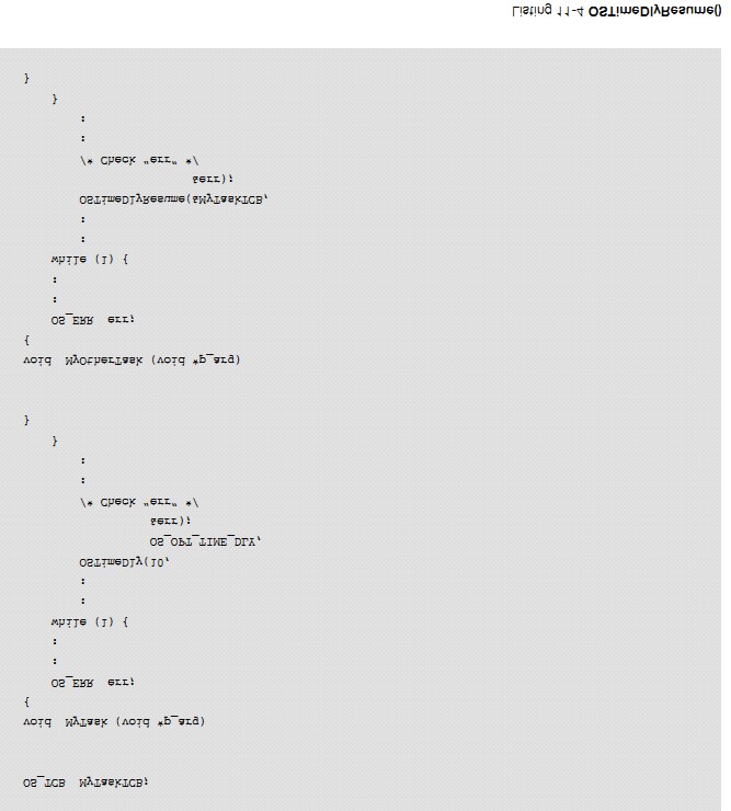
ÿ��ʱ���жϷ���ʱ uC/OS-III �����ʱ������ֵ��ͨ���������ֵ�ܴ�ſ���ϵͳ�ϵ���˶ʱ�䡣
��C/OS-III
increments a tick counter every time a tick interrupt occurs. This counter
allows the application to make coarse time measurements and have some notion of
time (after power up).
OSTimeGet()�ܻ��ʱ������ֵ��
OSTimeGet()
allows the user to take a snapshot of the tick counter. As shown in a previous
section, use this value to delay a task for a specific number of ticks and
repeat this periodically without losing track of time.
OSTimeSet()�����û�����ʱ������ֵ����Ȼ uC/OS-III �������ֲ������������������ʱ�����ء�
OSTimeSet()
allows the user to change the current value of the tick counter. Although
��C/OS-III allows for this, it is recommended to use this function with great
care.
��ʱ���жϷ���ʱ��ʱ�� ISR ����������������uC/OS-III �������������ʱ������ֵ��OSTimeTick()�� uC/OS-III ���ڲ�������
The
tick Interrupt Service Routine (ISR) must call this function every time a tick
interrupt occurs. ��C/OS-III uses this function to update time delays and
timeouts on other system calls. OSTimeTick() is considered an internal function
to ��C/OS-III.
uC/OS-III
�ṩ����ʱ�������û�������ʱ��Ϊ��λ��������ʱ��������Сʱ���֡��롢����Ϊ��λ��������ʱ����ʱ�ľ�ȷ��������ʱ����Ƶ�ʣ���ʱ����С�ֱ���Ϊʱ����
��C/OS-III
provides services to applications so that tasks can suspend their execution for
user-defined time delays. Delays are either specified by a number of clock
ticks or hours, minutes, seconds, and milliseconds.
�û����Ե��� OSTimeDlyResume()ʹ������ʱ״̬������ָ���
Application
code can resume a delayed task by calling OSTimeDlyResume(). However, its use
is not recommended because resumed task will not know that they were resumed as
opposed to the time delay expired.
ͨ�� OSTimeSet() ����ʱ������ֵ��ͨ�� OSTimeGet()��ȡʱ������ֵ��
��C/OS-III
keeps track of the number of ticks occurring since power up or since the number
of ticks counter was last changed by OSTimeSet(). The counter may be read by
the application code using OSTimeGet().
12��������ʱ������
uC/OS-III
�ṩ��������ʱ��������ش����� OS_TMR.C �У��������� OS_CFG.H �е� OS_CFG_TMR_EN Ϊ 1 ʱ������ʱ������ʹ�ܡ�{Ϊ�˼�࣬�����еĶ�ʱ����Ϊ������ʱ��}
��C/OS-III
provides timer services to the application programmer and code to handle timers
is found in OS_TMR.C. Timer services are enabled when setting OS_CFG_TMR_EN to
1 in OS_CFG.H.
��ʱ���ݼ������ֵ��������ֵΪ 0 �ģ����Ƕ�ʱ������ʱ��ͨ���ص�����ִ����Ӧ�IJ�������ر� LED������������������������ص��������û�����ģ�����ʱ������ʱ���Ա����á�Ȼ������Ҫ�ûص������������º��� OSTimeDly()��OSTimeDlyHMSM()�� OS???Pend()���������ܵ��¸ö�ʱ������������ɾ���ĺ�����
Timers
are down counters that perform an action when the counter reaches zero. The
user provides the action through a callback function (or simply callback). A
callback is a user-declared function that will be called when the timer
expires. The callback can be used to turn a light on or off, start a motor, or
perform other actions. However, it is important to never make blocking calls
within a callback function (i.e., call OSTimeDly(), OSTimeDlyHMSM(),
OS???Pend(), or anything that causes the timer task to block or be deleted).
Timers are useful in protocol stacks (retransmission timers, for example), and
can also be used to poll I/O devices at predefined intervals.
Ӧ���п��Զ����������ʱ���������ڴ������� RAM����uC/OS-III �Ķ�ʱ������ͨ������ OSTmr???()��ʼ�������¼ A
An
application can have any number of timers (limited only by the amount of RAM
available). Timer services in ��C/OS-III start with the OSTmr???() prefix, and
the services available to the application programmer are described in Appendix
A, ����C/OS-III API Reference Manual�� on page 375.
uC/OS-III
��ʱ���ķֱ��ʾ�����ʱ��Ƶ�ʣ�Ҳ���DZ���OS_CFG_TMR_TASK_RATE_HZ ��ֵ�������� Hz Ϊ��λ�ġ����ʱ�������Ƶ������Ϊ 10Hz�����ж�ʱ���ķֱ���Ϊʮ��֮һ�롣��ʵ�ϣ��������ڶ�ʱ�����Ƽ�ֵ����ʱ�����ڲ���ȷʱ��߶ȵ�����
The
resolution of all the timers managed by ��C/OS-III is determined by the
configuration constant: OS_CFG_TMR_TASK_RATE_HZ, which is expressed in Hertz
(Hz). So, if the timer task (described later) rate is set to 10, all timers
have a resolution of 1/10th of a second (ticks in the diagrams to follow). In
fact, this is the typical recommended value for the timer task. Timers are to
be used with ��coarse�� granularity.
uC/OS-III
�ṩ��һЩ�������ڹ�����ʱ����� 12-1
��C/OS-III
provides a number of services to manage timers as summarized in Table 12-1.
|
������
|
����
|
|
OSTmrCreate()
|
���������ö�ʱ��
|
|
OSTmrDel()
|
ɾ��һ����ʱ��
|
|
OSTmrRemainGet()
|
��ö�ʱ����ʣ������ֵ
|
|
OSTmrStart()
|
��ʼ��ʱ������
|
|
OSTmrStateGet()
|
��ö�ʱ����ǰ��״̬
|
|
OSTmrStop()
|
��ͣ��ʱ��
|
�� 12-1 ��ʱ���� API �ܽ�
��ʱ����ʹ��֮ǰ���뱻������ͨ������ OSTmrCreate()�������������������ز�����һ����ʱ���IJ���ģʽ�����ã��Ͳ��ܱ��Ķ�ֱ����ʱ����ɾ���������´�����OSTmrCreate()��ԭ�����£�
A
timer needs to be created before it can be used. Create a timer by calling
OSTmrCreate() and specify a number of arguments to this function based on how
the timer is to operate. Once the timer operation is specified, its operating
mode cannot be changed unless the timer is deleted and recreated. The function
prototype for OSTmrCreate() is shown below as a quick reference:
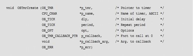
һ����ʱ���������������Ա���ʼ��ֹͣ����Ρ���ʱ�����Ա�����Ϊ 3 ��ģʽ��һ���Զ�ʱģʽ����ʼ��ʱ����ģʽ��û�г�ʼ�Ķ�ʱ�����г�ʼ��ʱ����ģʽ���г�ʼ�Ķ�ʱ����
Once
created, a timer can be started (or restarted) and stopped as often as is necessary.
Timers can be created to operate in one of three modes: One-shot, Periodic (no
initial delay), and Periodic (with initial delay).
�����������������ʱ����ݼ������ó�ʼ�Ķ�ʱֵ������ֵΪ 0 ʱ�ͻ���ûص�������ֹͣ��ʱ������ͼ 12-1����ʼ�Ķ�ʱֵͨ������ OSTmrSrart()���ã���ʱ����ʱ���ص����������ã��ٶ��ص������ڶ�ʱ��������ʱ���ṩ�������֮��ʱ��������������ֱ������ OSTmrStart()�����¿�����
As
its name implies, a one-shot timer will countdown from its initial value, call
the callback function when it reaches zero, and stop. Figure 12-1 shows a
timing diagram of this operation. The countdown is initiated by calling
OSTmrStart(). At the completion of the time delay, the callback function is
called, assuming a callback function was provided when the timer was created.
Once completed, the timer does not do anything unless restarted by calling
OSTmrStart(), at which point the process starts over.
ͨ������ OSTmrStop()ֹͣ��ʱ����
Terminate
the countdown process of a timer (before it reaches zero) by calling
OSTmrStop(). In this case, specify that the callback function be called or not.
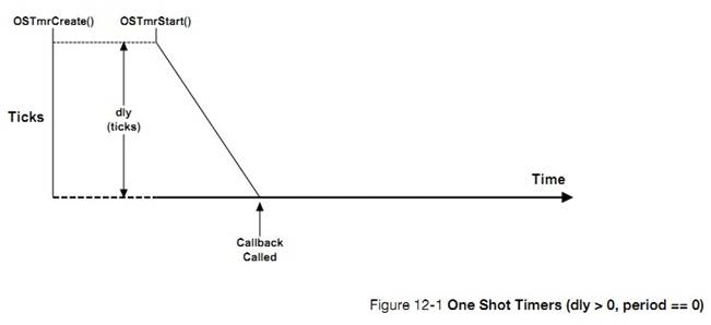
��ͼ 12-2 ��ʾ���ڶ�ʱֵΪ 0 ֮ǰ���� OSTmrStart()��һ���Զ�ʱ�����ٴδ�����������Կ��Ա�����ģ�⿴�Ź��Ĺ��ܡ�
As
shown in Figure 12-2, a one-shot timer is retriggered by calling OSTmrStart()
before the timer reaches zero. This feature can be used to implement watchdogs
and similar safeguards.
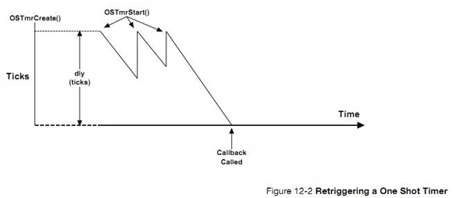
��ͼ 12-3 ��ʾ����ʱ��������Ϊ��ʼ��ʱ����ģʽ������ʱ������ʱ���ص����������ã���ʱֵ����ʱ����ֵ���أ���������Ե��ظ���
As
indicated in Figure 12-3, timers can be configured for periodic mode. When the
countdown expires, the callback function is called, the timer is automatically
reloaded, and the process is repeated. If specifying a delay of zero (i.e., dly
== 0) when the timer is created, when started, the timer immediately uses the
��period�� as the reload value. Calling OSTmrStart() at any point in the
countdown restarts the process.
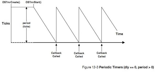
��ͼ 12-4 ��ʾ����ʱ�����Ա�����Ϊ�г�ʼ��������ģʽ����һ���ڵĵݼ�ֵ��
OSTmrCreate()�еIJ���"dly"���ã��Ժ������ֵ��"period"ֵȷ�������� OSTmrStart()���¿�ʼ��
As
shown in Figure 12-4, timers can be configured for periodic mode with an
initial delay that is different than its period. The first countdown count
comes from the ��dly�� argument passed in the OSTmrCreate() call, and the reload
value is the ��period��. Calling OSTmrStart() restarts the process including the
initial delay.
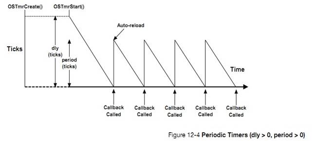
12-4-1 �ڲ���ʱ������-��ʱ��״̬
ͼ 12-5 ��ʾ�˶�ʱ����״̬ͼ
Figure
12-5 shows the state diagram of a timer.
������� OSTmrStateGet()��ö�ʱ����״̬����Ȼ��Ҳ���Ե���
OSTmrRemainGet()���ʣ�ඨʱʱ�䡣��ʱֵ����ʱ��Ϊ��λ�ġ����ʱ����ʱ����Ƶ����Ϊ 10Hz����ô��ʱֵ����Ϊ 50 ��ζ����ʱ5 �롣�����ʱ����ֹͣ�����䶨ʱֵҲ����ֹͣ��ֱ����ʱ�����ָ�ʱ����ʱ��ֵ��������ʱ������ݼ���
Tasks
can call OSTmrStateGet() to find out the state of a timer. Also, at any time
during the countdown process, the application code can call OSTmrRemainGet() to
find out how much time remains before the timer reaches zero (0). The value
returned is expressed in ��timer ticks.�� If timers are decremented at a rate of
10 Hz then a count of 50 corresponds to 5 seconds. If the timer is in the stop
state, the time remaining will correspond to either the initial delay (one shot
or periodic with initial delay), or the period if the timer is configured for
periodic without initial delay.
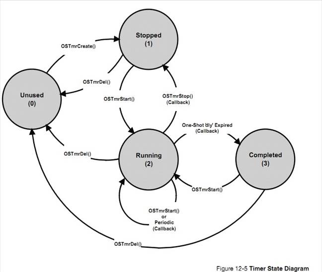
F12-5��1��"Unused"״̬��ζ�Ŷ�ʱ����δ���������Ѿ���ɾ�������仰˵��uC/OS-III ��֪���ö�ʱ�������״̬��
F12-5(1) The ��Unused�� state is a timer that has
not been created or has been ��deleted.�� In other words, ��C/OS-III does not know
about this timer.
F12-5��2���������˶�ʱ��������� OSTmrStop()����ʱ���ᴦ��ֹͣģʽ��
F12-5(2) When creating a timer or calling
OSTmrStop(), the timer is placed in the ��stopped�� state.
F12-5��3�������� OSTmrStart()��ʱ����������״̬��
F12-5(3) A timer is placed in running state when
calling OSTmrStart(). The timer stays in that state unless it��s stopped,
deleted, or completes its one shot.
F12-5��4��һ���Զ�ʱģʽ�Ķ�ʱ����ʱ�����������״̬"Completed"��
F12-5(4) The ��Completed�� state is the state a
one-shot timer is in when its delay expires.
12-4-2 ��ʱ���ڲ���������OS_TMR
��ʱ���� uC/OS-III �е��ں˶�������������Ϊ OS_TMR����OS.H�������б� 12-1 ��ʾ��uC/OS-III
�й�����ʱ������ش������ļ� OS_TMR.C �С��ڱ���ʱͨ������ OS_CFG.H �е� OS_CFG_TMR_EN Ϊ 1 ������ʱ�����ܡ�
A
timer is a kernel object as defined by the OS_TMR data type (see OS.H) as shown
in Listing 12-1.
The
services provided by ��C/OS-III to manage timers are implemented in the file
OS_TMR.C. A ��C/OS-III licensee has access to the source code. In this case,
timer services are enabled at compile time by setting the configuration
constant OS_CFG_TMR_EN to 1 in OS_CFG.H.
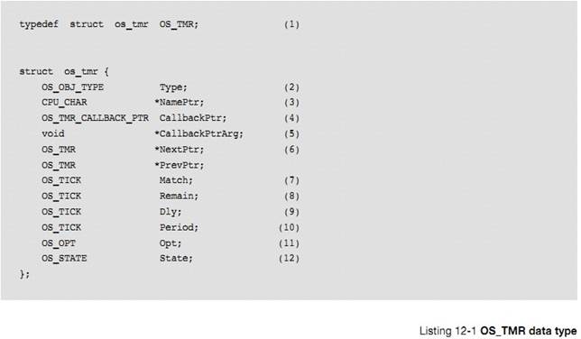
L12-1��1���� uC/OS-III �У����еĽṹ�嶼����һ���������͡���ʵ�ϣ����е��������Ͷ�����"OS_"Ϊ��ͷ�IJ���ȫ����д������ʱ��������ʱ������������Ϊ
OS_TMR �ı������������ʱ����
L12-1(1) In ��C/OS-III, all
structures are given a data type. In fact, all data types start with ��OS_�� and are all uppercase. When a timer is
declared, simply use OS_TMR as the data type of the variable used to declare
the timer.
L12-1��2���ṹ�忪ʼ��һ��"Type"��uC/OS-III ����ͨ�������������Ǹ���ʱ���������ں˶���Ľṹ���ײ�Ҳ��"Type"������������贫��һ���ں˶���uC/OS-III ����"Type"���Ƿ�Ϊ������������͡����磬���������Ϣ���� QS_Q ����ʱ����uC/OS-III �����Ƿ�Ϊ��Ϣ���б��ύ�������ش�����š�
L12-1(2) The structure starts with a ��Type�� field,
which allows it to be recognized by ��C/OS-III as a timer. Other kernel objects
will also have a ��Type�� as the first member of the structure. If a function is
passed a kernel object, ��C/OS-III is able to confirm that it is passed the
proper data type. For example, if passing a message queue (OS_Q) to a timer
service (for example OSTmrStart()) then ��C/OS-III will be able to recognize
that an invalid object was passed, and return an error code accordingly.
L12-1��3��ÿ���ں˶����Ա������������ڵ�ʽ���� uC/Probe �ĵ��ԡ�����һ��ָ���ں˶�������ָ�롣
L12-1(3) Each kernel object can be given a name
for easier recognition by debuggers or ��C/Probe. This member is simply a
pointer to an ASCII string which is assumed to be NUL terminated.
L12-1��4��.CallbackPtr ��һ��ָ������ָ�룬��ָ��ĺ��������ص�����������ʱ������ʱ�ص����������á������ʱ������ʱ��ָ��ֵΪ NULL���ص����������ᱻ���á�
L12-1(4) The .CallbackPtr member is a pointer to a
function that is called when the timer expires. If a timer is created and
passed a NULL pointer, a callback would not be called when the timer expires.
L12-1��5�����ص�������Ҫ����һ������ʱ��.CallbackPtr ��Ϊ NULL�����������ͨ����ָ�봫�ݸ��ص�������
L12-1(5) If there is a non-NULL .CallbackPtr then
the application code could have also specified that the callback be called with
an argument when the timer expires.
This
is the argument that would be passed in this call.
L12-1��6��.NextPtr ��.PrevPtr
����ָ�룬���ڽ���ʱ�����ӳ�һ��˫��������
L12-1(6) .NextPtr and .PrevPtr are pointers used
to link a timer in a doubly linked list. These are described later.
L12-1��7�� ����ʱ���������еı��� OSTmrTickCtr ��ֵ����.Match ֵʱ����ʱ��������
L12-1(7) A timer expires when the timer manager
variable OSTmrTickCtr reaches the value stored in a timer��s .Match field. This
is also described later.
L12-1��8��.Remain �б����˾ඨʱ���������ж��ٸ�ʱ�������ֵÿ����һ�� OS_CFG_TMR_WHEEL_SIZE���Ժ�˵���������¡�
L12-1(8) The .Remain contains the amount of time
remaining for the timer to expire. This value is updated once per
OS_CFG_TMR_WHEEL_SIZE (see OS_CFG_APP.H) that the timer task executes
(described later). The value is expressed in multiples of
1/OS_CFG_TMR_TASK_RATE_HZ of a second (see OS_CFG_APP.H).
L12-1��9��.Dly ������˶�ʱ���Ķ�ʱֵ�����ֵ��ʱ��Ϊ��С��λ��
L12-1(9)
The .Dly field contains the one-shot time when the timer is configured (i.e.,
created) as a one-shot timer and the initial delay when the timer is created as
a periodic timer. The value is expressed in multiples of
1/OS_CFG_TMR_TASK_RATE_HZ of a second (see OS_CFG_APP.H).
L12-1��10��.Period �Ƕ�ʱ���Ķ�ʱ���ڣ���������Ϊ����ģʽʱ����
���ֵ��ʱ��Ϊ��С��λ��
L12-1(10) The .Period is the timer period when the timer
is created to operate in periodic mode. The value is expressed in multiples of 1/OS_CFG_TMR_TASK_RATE_HZ of a second
(see OS_CFG_APP.H).
L12-1��11��.Opt ������˴��ݸ�
OSTmrCreate()�IJ�������ѡ����
L12-1(11) The .Opt field contains options as passed to
OSTmrCreate().
L12-1��12��.State �а����˶�ʱ����ǰ��״̬����ͼ 12-5����
��ʹ�˽� OS_TMR �ṹ������ݣ��û�����Ҳ����ֱ�ӷ�����Щ���ݡ�����ͨ��
uC/OS-III �ṩ�� API ���ʡ�
L12-1(12) The .State field represents the current state
of the timer (see Figure 12-5).
Even
if the internals of the OS_TMR data type are understood, the application code
should never access any of the fields in this data structure directly. Instead,
always use the Application Programming Interfaces (APIs) provided with
��C/OS-III.
12-4-3 �ڲ���ʱ������������ʱ������
ͨ������ OS_CFG.H �е� OS_CFG_TMR_EN Ϊ 1 ʹ�ܶ�ʱ������OS_TmrTask() ������������ȼ�ͨ�� OS_CFG_APP.H �е� OS_CFG_TMR_TASK_PRIO ���á�OS_TmrTask()�����ȼ�ͨ��������Ϊ�еȴ�С��
OS_TmrTask()
is a task created by ��C/OS-III (assumes setting OS_CFG_TMR_EN to 1 in OS_CFG.H)
and its priority is configurable by the user through ��C/OS-III��s configuration
file OS_CFG_APP.H (see OS_CFG_TMR_TASK_PRIO). OS_TmrTask() is typically set to
a medium priority.
OS_TmrTask()��һ�������Ե�������ʹ��ʱ���ж�Դ��Ϊ����ʱ�Ӽ���Դ��Ȼ������ʱ��ͨ�������ϵ͵������źţ�����Ϊ 10Hz �ȣ������������ź��Ǵ�ʱ���ź��з�Ƶ�����ġ����ʱ��Ƶ��Ϊ1000Hz����ʱ����Ҫ��Ƶ��Ϊ 10Hz����ô��ʱ�������豻����Ϊÿ100 ��ʱ������һ���źţ�Ҳ���Ƿ�ƵֵΪ 100����ͼ 12-6
OS_TmrTask()
is a periodic task and uses the same interrupt source used to generate clock
ticks. However, timers are generally updated at a slower rate (i.e., typically
10 Hz or so) and thus, the timer tick rate is divided down in software. If the
tick rate is 1000 Hz and the desired timer rate is 10 Hz then the timer task
will be signaled every 100th tick interrupt as shown in Figure 12-6.
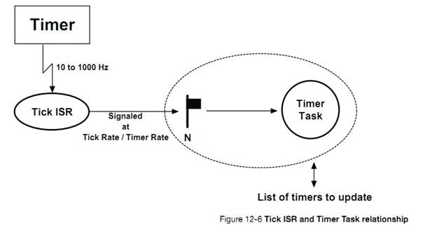
ͼ 12-7 ��ʱ���������������������
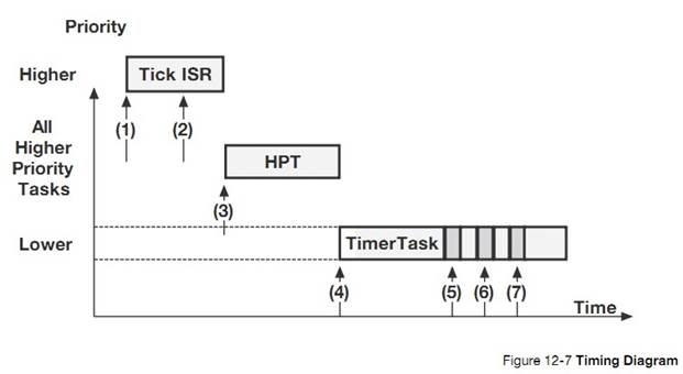
F12-7��1���жϲ���
F12-7(1) The tick ISR occurs and assumes
interrupts are enabled and executes.
F12-7��2��ʱ�� ISR ���ʱ������
F12-7(2) The tick ISR signals the tick task that
it is time for it to update timers.
F12-7��3��Ȼ�����и����ȼ�������Ҫ��ִ�С���ˣ�uC/OS-III �л��������ȼ�����
F12-7(3) The tick ISR terminates, however there
are higher priority tasks that need to execute (assuming the timer task has a
lower priority). Therefore, ��C/OS-III runs the higher priority task(s).
F12-7��4�������еĸ����ȼ�����ִ����ϣ�uC/OS-III �л�����ʱ����������������ʱ��������
F12-7(4) When all higher priority tasks have
executed, ��C/OS-III switches to the timer task and determines that there are
three timers that expired.
F12-7��5����һ����ʱ���Ļص�������ִ�С�
F12-7(5) The callback for the first timer is
executed.
F12-7��6���ڶ�����ʱ���Ļص�������ִ�С�
F12-7(6) The callback for the second expired timer
is executed.
F12-7��7) ��������ʱ���Ļص�������ִ�С�
F12-7(7) The callback for the third expired timer
is executed.
��һЩ��Ȥ��������ע�⣺
There
are a few interesting things to notice:
�� �ص��������ڶ�ʱ�������л���ִ�еġ�����ζ�Ŷ�ʱ��������Ҫ���㹻�Ķ�ջ�ռ乩�ص�����ȥִ�С�
Execution
of the callback functions is performed within the context of the timer task.
This means that the application code will need to make sure there is sufficient
stack space for the timer task to handle these callbacks.
�� �ص��������ڸ��ݶ�ʱ�����������δ�ŵġ�����������ص����������α�ִ�еġ�
The
callback functions are executed one after the other based on the order they are
found in the timer list.
�� ��ʱ�������ִ��ʱ������ڣ��ж��ٸ���ʱ��������ִ�ж�ʱ���еĻص����������ʱ�䡣��Ϊ�ص��������û��ṩ�������ܴܺ�̶���Ӱ���˶�ʱ�������ִ��ʱ�䡣
The
execution time of the timer task greatly depends on how many timers expire and
how long each of the callback functions takes to execute. Since the callbacks
are provided by the application code they have a large influence on the
execution time of the timer task.
�� ��ʱ���еĻص��������ܵȴ��¼��ķ�������Ϊ�������ܻ��ö�ʱ��������
The
timer callback functions must never wait on events that would delay the timer
task for excessive amounts of time, if not forever.
�� �ص�������ִ��ʱ����������������������ûص����������ܵض̡�Callbacks are called with the scheduler locked, so you
should ensure that callbacks execute as quickly as possible.
12-4-4 �ڲ���ʱ������������ʱ���б�
��Щ����£�uC/OS-III ����Ҫά���ϰٸ���ʱ����ʹ�ö�ʱ���б������¶�ʱ���б���ռ�õ� CPU ʱ�䡣��ʱ���б�������ʱ���б�����ͼ 12-8 ��ʾ��
��C/OS-III
might need to literally maintain hundreds of timers (if an application requires
that many). The timer list management needs to be implemented such that it does
not take too much CPU time to update the timers. The timer list works similarly
to a tick list as shown in Figure 12-8.
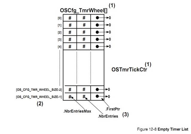
F12-8��1����ʱ���б����������֣���(OSCfg_TmrWheel[])�Ͷ�ʱ����������(OSTmrTickCtr)��
F12-8(1) The timer list consists of a table
(OSCfg_TmrWheel[]) and a counter (OSTmrTickCtr).
F12-8��2�����а����� OS_CFG_TMR_WHEEL_SIZE ����¼�������ڱ���ʱ�趨�ģ��� OS_CFG_APP.H������¼�Ķ��ٽ����ڴ�������RAM �ռ䡣�Ƽ�������ֵΪ��ʱ���� /4 �����Ƽ����� OS_CFG_TMR_WHEEL_SIZE Ϊż��ֵ�����仰˵�������ʱ�������� 10Hz �ģ��������� OS_CFG_TMR_WHEEL_SIZE Ϊ 10�������� 11 ���档
F12-8(2) The table contains up to
OS_CFG_TMR_WHEEL_SIZE entries, which is a compile time configuration value (see
OS_CFG_APP.H). The number of entries depends on the amount of RAM available to
the processor and the maximum number of timers in the application. A good
starting point for OS_CFG_TMR_WHEEL_SIZE might be: #Timers/4. It is not
recommended to make OS_CFG_TMR_WHEEL_SIZE an even multiple of the timer task
rate. In other words, if the timer task is 10 Hz, avoid setting
OS_CFG_TMR_WHEEL_SIZE to 10 or 100 (use 11 or 101 instead). Also, use prime
numbers for the timer wheel size. Although it is not really possible to plan at
compile time what will happen at run time, ideally the number of timers waiting
in each entry of the table is distributed uniformly.
F12-8
�� 3 �����е�ÿ����¼����3�����飺.NbrEntriesMax��.NbrEntries��.FirstPtr��.NbrEntriesMax �����ü�¼���ж��ٸ���ʱ����.NbrEntriesMax �����ü�¼�����ʱ����˶��ٸ���ʱ����.FirstPtr ָ��ǰ��¼�Ķ�ʱ��������
��ʱ�� ISR ��������ʱ������ʱ����ʱ��������� OS_TmrTask() ������ʱ������ֵ��
F12-8(3)
Each entry in the table contains three fields: .NbrEntriesMax, .NbrEntries and
.FirstPtr. .NbrEntries indicates how many timers are linked to this table
entry. .NbrEntriesMax keeps track of the highest number of entries in the
table. Finally, .FirstPtr contains a pointer to a doubly linked list of timers
(through the tasks OS_TMR) belonging into the list at that table position.
ͨ������ OSTmrStart()����ʱ�����뵽��ʱ���б��С�Ȼ������ʱ�������ڱ�ʹ��֮ǰ��������
The
counter is incremented by OS_TmrTask() every time the tick ISR signals the
task.
��һ�����Ӳ���һ����ʱ�������뵽��ʱ���б��еĹ��̡����б� 12-2 �� ʾ �� �����ȼٶ���ʱ���б��ǿյģ�����OS_CFG_TMR_WHEEL_SIZE
Ϊ 9����ǰ�� OSTmrTickCtr Ϊ 12������ OSTmrStart()ʱ��ʱ�������붨ʱ���б����ٶ���ʱ������ʱ��������ʱΪ 1�������������һ���Զ�ʱ��
Timers
are inserted in the timer list by calling OSTmrStart(). However, a timer must
be created before it can be used.
An
example to illustrate the process of inserting a timer in the timer list is as
follows. Let��s assume that the timer list is completely empty,
OS_CFG_TMR_WHEEL_SIZE is configured to 9, and the current value of OSTmrTickCtr
is 12 as shown in Figure 12-9. A timer is placed in the timer list when calling
OSTmrStart(), and assumes that the timer was created with a delay of 1 and that
this timer will be a one-shot timer as follows:
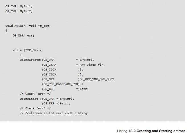
��Ϊ OSTmrTickCtr ��ֵΪ 12����ʱ���Ķ�ʱֵΪ 1���� OSTmrTickCtr ��ֵ��Ϊ 13 ʱ��ʱ����������ʱ���ᱻ���� OSCfg_TmrWheel[]��������ʽ���㣺
Since
OSTmrTickCtr has a value of 12, the timer will expire when OSTmrTickCtr reaches
13, or during the next time the timer task is signaled. Timers are inserted in
the OSCfg_TmrWheel[] table using the following equation:
MatchValue=OSTmrTickCtr+dly
Index intoOSCfg_TmrWheel[]=MatchValue%
OS_CFG_TMR_WHEEL_SIZE
"dly"�Ǵ��ݸ� OSTmrCreate()�ĵ�������������������ʽ���뱾����
���ǻ�õ����µ�ʽ��
MatchValue =13
Index into OSCfg_TmrWheel[] =4
��ʱ�������뵽 OScfg_TmrWheel[4] �У�����������£�OS_TMR �����ڶ����е���λ�� (OSCfg_TmrWheel[4].FirstPtr ָ����� OS_TMR)���������� 4 �ļ���ֵ������OSCfg_TmrWheel[4].NbrEntries ��ʱΪ 1����ƥ��ֵ"MatchValue"������ OS_TMR ��.Match �С���Ϊ�������� 4 ��Ψһһ����ʱ����.NextPtr ��.PrevPtr ��ָ�� NULL��
The timer
is entered at index 4 in the timer wheel, OSCfg_TmrWheel[]. In this case, the
OS_TMR is placed at the head of the list (i.e., pointed to by
OSCfg_TmrWheel[4].FirstPtr), and the number of entries at index 4 is
incremented (i.e., OSCfg_TmrWheel[4].NbrEntries will be 1). ��MatchValue�� is
placed in the OS_TMR field .Match. Since this is the first timer inserted in
the timer list at index 4, the .NextPtr and .PrevPtr both point to NULL.
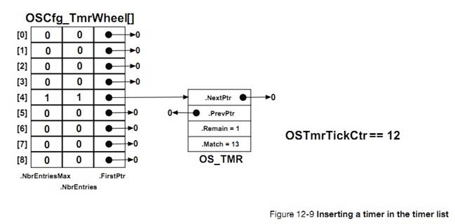
�� �� �� �� �� �� ʾ �� ��
�� �� �� �� ʱ �� �� �� �� ��
The
code below shows creating and starting another timer. This is performed
��before�� the timer task is signaled.
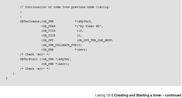
uC/OS-III
�����ƥ��ֵ������ֵ���£�
��C/OS-III
will calculate the match value and index as follows:
MatchValue =12+10 =22
Index into OSCfg_TmrWheel[] =22%9 =4
�ڶ�����ʱ��Ҳ�����뵽����Ϊ 4 �ı���¼�У���ͼ 12-10�����б����·��䣬ʣ��ʱ�����ٵĶ�ʱ�����ŵ����е��ײ���ʣ��ʱ�����Ķ�ʱ�����ŵ����е�β����
The
��second timer�� will be inserted at the same table entry as shown in Figure
12-10, but sorted so that the timer with the least amount of time remaining
before expiration is placed at the head of the list, and the timer with the
longest to wait at the end.
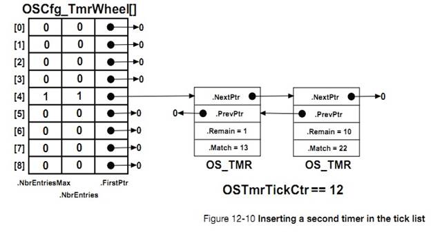
����ʱ������ִ�У��� OS_TMR.C �е� OS_TmrTask()���������ȵ��� OSTmrTickCtr��Ȼ��������е�������¼�豻���¡�Ȼ�����������¼���ж�ʱ�����У�.FirstPtr ��Ϊ NULL����ÿ�� OS_TMR ���ᱻ�����.Match �Ƿ��� OSTmrTickCtr ��ȡ������ȣ������ʱ���ᱻ�Ƴ��ö��У�Ȼ��
OS_TmrTask()���������ʱ���Ļص��������ٶ������ʱ��������ʱ�лص��������������ü�¼����������ֱ��û�ж�ʱ����.Match ֵ�� OSTmrTickCtr ƥ�䡣ע����ǣ����лᱻ��������
When
the timer task executes (see OS_TmrTask() in OS_TMR.C), it starts by
incrementing OSTmrTickCtr and determines which table entry (i.e., spoke) it
needs to update. Then, if there are timers in the list at this entry (i.e.,
.FirstPtr is not NULL), each OS_TMR is examined to determine whether the .Match
value ��matches�� OSTmrTickCtr and, if so, the OS_TMR is removed from the list
and OS_TmrTask() calls the timer callback function, assuming one was defined
when the timer was created. The search through the list terminates as soon as
OSTmrTickCtr does not match the timer��s .Match value. There is no point in
looking any further in the list since the list is already sorted.
OS_TmrTask()����Ĵֹ�������������������״̬�½��еġ�Ȼ������Ϊ���лᱻ���·��䣨�����������Ա���������е�ʱ���dz��̵ģ�Ҳ�����ٽ�λ�dz��̵ġ�
Note
that OS_TmrTask() does most of its work with the scheduler locked. However,
because the list is sorted, and the search through the list terminates as soon
as there no longer is a match, the critical section should be fairly short.
����ʱ���ļ���ֵ�ݼ�Ϊ 0 ʱ��ʱ����������ִ�лص��������ص��������û����塣
Timers
are down counters that perform an action when the counter reaches zero. The
action is provided by the user through a callback function.
uC/OS-III
�����û��������������Ķ�ʱ����ֻ�����ڴ�������RAM ��С����
�ص������ڶ�ʱ�������б����ã������лص�����ʱ���������ڱ���״̬���ص�����Խ��Խ�ã��Ҳ����ڻص������еȴ��¼�����������ʱ������ᱻ���𣬵��¶�ʱ�����������
��C/OS-III
allows application code to create any number of timers (limited only by the
amount of RAM available).
The
callback functions are executed in the context of the timer task with the
scheduler locked. Keep callback functions as short and as fast as possible and
do not have the callbacks make blocking calls.
13����Դ����
����½ڻ���ܹ�����Դ��صķ�������Դ�����ǣ���������̬�Ļ�ȫ�ֵģ����ṹ�塢�ڴ�ռ䡢I/O �ȡ�
This
chapter will discuss services provided by ��C/OS-III to manage shared resources.
A shared resource is typically a variable (static or global), a data structure,
table (in RAM), or registers in an I/O device.
�����Ƽ��� mutex ����������Դ��������½��У������ķ���Ҳ�ᱻ���ܡ�
When
protecting a shared resource it is preferred to use mutual exclusion
semaphores, as will be described in this chapter. Other methods are also
presented.
���������ܻ�ͬʱҪ��ռ����Դ���ڴ�ռ䡢ȫ�ֱ�����ָ�롢���������б������λ������ȡ�ͨ��������Դ�������ͨ�Ž���Ƚϼ���Ȼ�����������ľ����ͷ�ֹ��Դ���ƻ��Ƿdz���Ҫ�ġ�
Tasks
can easily share data when all tasks exist in a single address space and can
reference global variables, pointers, buffers, linked lists, ring buffers, etc.
Although sharing data simplifies the exchange of information between tasks, it
is important to ensure that each task has exclusive access to the data to avoid
contention and data corruption.
���磬�����ʵ���ֱ��ļ�ʱ���ܣ���ô������Сʱ�����ӡ��롣�ɶ���Ϊ TimeOfDay()�������б� 13-1 ��ʾ
For
example, when implementing a module that performs a simple time-of-day
algorithm in software, the module obviously keeps track of hours, minutes and
seconds. The TimeOfDay() task may appear as that shown in Listing 13-1.
����һ�£�����������ķ��ӵ����� 60 ������Ϊ 0���ҽ�Ҫ����Сʱ��ʱ���жϷ����ˣ������ȼ�������ռ CPU����ʱ�����ȼ������ȡ��ǰʱ�䣬����ʲô�����������Ϊ�����ж�ǰСʱû�б����������Ը����ȼ����������ֵ�Ǵ���ģ�������������һ��Сʱ��
Imagine
if this task was preempted by another task because an interrupt occurred, and,
the other task was more important than the TimeOfDay() task) after setting the
Minutes to 0. Now imagine what will happen if this higher priority task wants
to know the current time from the time-of-day module. Since the Hours were not
incremented prior to the interrupt, the higher-priority task will read the time
incorrectly and, in this case, it will be incorrect by a whole hour.
�� TimeOfDay()�����и���ʱ�䲿�ֵĴ�����в��ɷָ��ԡ���Щ�������Ա���Ϊ�ǹ�����Դ���Ҵ���Ҫ������Щ����ʱ�������ٽ�ε���ʽ������Щ������uC/OS-III �ṩ mutex ������Щ������Դ���������ٽ�Ρ�
The
code that updates variables for the TimeOfDay() task must treat all of the
variables indivisibly (or atomically) whenever there is possible preemption.
Time-of-day variables are considered shared resources and any code that
accesses those variables must have exclusive access through what is called a
critical section. ��C/OS-III provides services to protect shared resources and
enables the easy creation of critical sections.
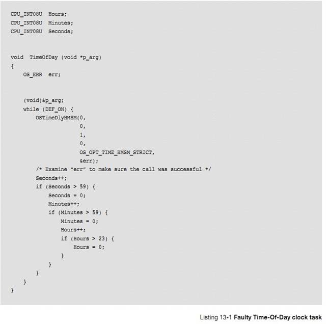
�ֶ�ռ��Դ�ķ������Ǵ����ٽ�Σ����жϷ�ʽ������������ʽ���ź�����ʽ��mutex ��ʽ���������ֱ������ƾ����ڷ��ʹ�����Դ�Ĵ��볤�ȣ���� 13-1 ��ʾ
The most
common methods of obtaining exclusive access to shared resources and to create critical
sections are: �� disabling interrupts�� disabling the scheduler�� using semaphores��
using mutual exclusion semaphores (a.k.a. a mutex)��The mutual exclusion mechanism used depends on how fast the
code will access a shared resource, as shown in Table 13-1.
|
��Դ������ʽ
Resource Sharing Method
|
ʲôʱ�����
When should you use?
|
|
���жϷ�ʽ
Disable/Enable Interrupts
|
�ܺܿ�ؽ������ʹ�����Դ�����Ƽ�ʹ�����ַ�������Ϊ�ᵼ���ж��ӳ�
When access to shared resource is very quick (reading
from or writing to few variables) and access is faster than ��C/OS-III��s interrupt
disable time.
It is highly recommended to not use this method as it
impacts interrupt latency.
|
|
����������ʽ
Locking/Unlocking the Scheduler
|
���ʹ�����Դ�ȽϾ�ʱ
When access time to the shared resource is longer
than ��C/OS-III��s interrupt disable time, but shorter than ��C/OS-III��s scheduler lock time.
Locking the scheduler has the same effect as making
the task that locks the scheduler the highest-priority task.
It is recommended not to use this method since it
defeats the purpose of using ��C/OS-III.
However, it is a better method than disabling interrupts, as it does not
impact interrupt latency.
|
|
�ź�����ʽ
Semaphores
|
���ù�����Դ�������������ʹ��ʱ���á����ź������ܻ�������ȼ����á�Ȼ�����ź�����ʽ��ִ��ʱ������ mutex ��ʽ
When all tasks that need to access a shared resource
do not have deadlines. This is because semaphores may cause unbounded
priority inversions (described later). However, semaphore services are
slightly faster (in execution time) than mutual-exclusion semaphores.
|
|
mutex ��ʽ
Mutual Exclusion Semaphores
|
�Ƽ�ʹ�����ַ������ʹ�����Դ�����䵱����Ҫ���ʵĹ�����Դ�н�ֹʱ�䡣
This is the preferred method for accessing shared resources,
especially if the tasks that need to access a shared resource have deadlines.
uC/OS-III �� mutex �����õ����ȼ��������ɷ�ֹ���ȼ����á�
Remember that ��C/OS-III��s mutual exclusion semaphores
have a built-in priority inheritance mechanism, which avoids unbounded priority
inversions.
Ȼ����mutex ��ʽ�����ź�����ʽ�����˸���������ı��ź��������ȼ�
However, mutual exclusion semaphore services are
slightly slower (in execution time) than semaphores since the priority of the
owner may need to be changed, which requires CPU processing.
|
�� 13-1 ��Դ����
��ռ������Դ������������ǹ��жϣ����б� 13-2 ��ʾ
The
easiest and fastest way to gain exclusive access to a shared resource is by
disabling and enabling interrupts, as shown in the pseudo-code in Listing 13-2.
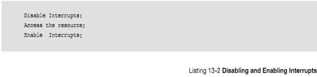
��C/OS-III
uses this technique (as do most, if not all, kernels) to access certain
internal variables and data structures, ensuring that these variables and data
structures are manipulated atomically.
Ȼ������/���ж��Ǻ� CPU ��صIJ���������ش��뱻������ CPU ��ص��ļ��У��� CPU.H����uC/OS-III ���� CPU ��ص�ģ����� uC/CPU��ÿ�ּܹ��� CPU ����Ҫ��������Ӧ�� uC/CPU �ļ���
However,
disabling and enabling interrupts are actually CPU-related functions rather
than OS-related functions and functions in CPU-specific files are provided to
accomplish this (see the CPU.H file of the processor being used). The services
provided in the CPU module are called ��C/CPU. Each different target CPU
architecture has its own set of ��C/CPU-related files.
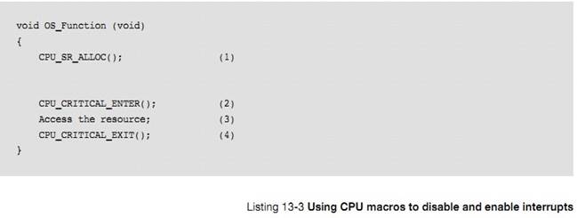
L13-3��1����ʹ�ÿ�/���жϺ�ʱ
CPU_SR_ALLOC()���DZ���ġ������Ϊһ�����صı��������˴洢�ռ����ڱ�����ж�ǰ�� CPU ״̬�Ĵ��� SR��{�ٽ��ʱ���ж�ǰֻ�豣��
SR}
L13-3(1)
The CPU_SR_ALLOC() macro is required when the other two macros that disable/enable
interrupts are used. This macro simply allocates storage for a local variable
to hold the value of the current interrupt disable status of the CPU. If
interrupts are already disabled we do not want to enable them upon exiting the
critical section.
L13-3��2��CPU_CRITICAL_ENTER()��ȫ���жϡ�
L13-3(2) CPU_CRITICAL_ENTER() saves the current
state of the CPU interrupt disable flag(s) in the local variable allocated by
CPU_SR_ALLOC() and disables all maskable interrupts.
L13-3��3�������ٽ��ʱ���ᱻ�жϻ������ϣ���Ϊ�жϱ��رա�
���仰˵���ٽ�εIJ�����ԭ���Եġ�
L13-3(3) The critical section of code is then
accessed without fear of being changed by either an ISR or another task because
interrupts are disabled. In other words, this operation is now atomic.
L13-3��4��CPU_CRITICAL_EXIT()��������ر����лָ����ж�ǰ�� CPU ״̬������ȫ���жϡ�
L13-3(4) CPU_CRITICAL_EXIT() restores the
previously saved interrupt disable status of the CPU from the local variable.
CPU_CRITICAL_ENTER()�� CPU_CRITICAL_EXIT()�����ɶԵ�ʹ�á����ж�ʱ��Խ��Խ�ã���Ȼ��Ӱ��ϵͳ��Ӧ�ⲿ�¼��ļ�ʱ�ԡ�
CPU_CRITICAL_ENTER()
and CPU_CRITICAL_EXIT() are always used in pairs. Interrupts should be disabled
for as short a time as possible as disabling interrupts impacts the response of
the system to interrupts. This is known as interrupt latency. Disabling and
enabling is used only when changing or copying a few variables.
���ٽ�κܶ�ʱ����ʹ�ù��жϷ�����
Note,
this is the only way that a task can share variables or data structures with an
ISR. ��C/CPU provides a way to actually measure interrupt latency.
ע����ǣ�ֻ�����ַ����ſ���������� ISR ������Դ��
When
using ��C/OS-III, interrupts may be disabled for as much time as ��C/OS-III does,
without affecting interrupt latency. Obviously, it is important to know how
long ��C/OS-III disables interrupts, which depends on the CPU used.
Although
this method works, avoid disabling interrupts as it affects the responsiveness
of the system to real-time events.
���������Ҫ�� ISR ������Դ���Ϳ���ͨ���������������ʹ�����Դ�����б� 13-4 ��ʾ��
If
the task does not share variables or data structures with an ISR, disable and
enable ��C/OS-III��s scheduler while accessing the resource, as shown in Listing
13-4.
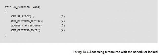
ʹ�����ַ������������Ϳ��������ķ��ʹ�����Դ��ע�⣬ֻ�е������������ж���ʹ�ܵģ�����ڴ����ٽ��ʱ�жϷ�����ISR ����ͻᱻִ�С��� ISR ��ĩβ��uC/OS-III �᷵��ԭ����ʹ ISR ���и����ȼ�����������
Using
this method, two or more tasks share data without the possibility of
contention. Note that while the scheduler is locked, interrupts are enabled and
if an interrupt occurs while in the critical section, the ISR is executed
immediately. At the end of the ISR, the kernel always returns to the
interrupted task even if a higher priority task is made ready to run by the
ISR. Since the ISR returns to the interrupted task, the behavior of the kernel
is similar to that of a non-preemptive kernel (while the scheduler is locked).
OSSchedLock()�� OSSchedUnlock()���Ա�Ƕ��� 250 ������OSSchedUnlock()�� OSSchedLock()�����õĴ�����ͬʱ�������ű�������
OSSchedLock()
and OSSchedUnlock() can be nested up to 250 levels deep. The scheduler is
invoked only when OSSchedUnlock() is called the same number of times the
application called OSSchedLock().
ֱ��������������uC/OS-III �л��������ȼ�����
After
the scheduler is unlocked, ��C/OS-III performs a context switch if a higher
priority task is ready to run.
uC/OS-III
�������û�����������ʱ��������{��������������ʱ�ȴ�ij�¼��ķ���}����Ȼ����������
��C/OS-III
will not allow the user to make blocking calls when the scheduler is locked. If
the application were able to make blocking calls, the application would most
likely fail.
��Ȼ�������������ͦ�ã�Ȼ����������Ӱ������ռʽ�ں˵ij��ԡ�
Although
this method works well, avoid disabling the scheduler as it defeats the purpose
of having a preemptive kernel. Locking the scheduler makes the current task the
highest priority task.
���ź�������ͬ���ĸ����Ǻ����ĵ��Կ�ѧ�� Edgser Dijkstra �� 1959 �귢���ġ��ڵ��������У��ź�����һ�����ڶ�������ȵ�Э����ơ�������ڿ��ƹ�����Դ�ķ��ʣ���������ͬ��������� 14 �¡�ͬ��������Ȼ���������ź�������α����ڿ��ƹ�����Դ�Ƿdz���Ҫ�ġ�
A
semaphore originally was a mechanical signaling mechanism. The railroad
industry used the device to provide a form of mutual exclusion for railroads
tracks shared by more than one train. In this form, the semaphore signaled
trains by closing a set of mechanical arms to block a train from a section of
track that was currently in use. When the track became available, the arm would
swing up and the waiting train would then proceed.
�ź�����һ����������������������Ҫ���Կ�ײſ��Է��ʹ�����Դ��ռ�ø���Դ��������ʹ�ø���Դ���ͷ���Դʱ������������ܹ����������Դ��
The
notion of using a semaphore in software as a means of synchronization was
invented by the Dutch computer scientist Edgser Dijkstra in 1959. In computer
software, a semaphore is a protocol mechanism offered by most multitasking
kernels. Semaphores, originally used to control access to shared resources, now
are used for synchronization as described in Chapter 14, ��Synchronization�� on
page 251. However, it is useful to describe how semaphores can be used to share
resources. The pitfalls of semaphores will be discussed in a later section.
A
semaphore was originally a ��lock mechanism�� and code acquired the key to this
lock to continue execution. Acquiring the key means that the executing task has
permission to enter the section of otherwise locked code. Entering a section of
locked code causes the task to wait until the key becomes available.
ͨ�����������͵��ź�������ֵ�ź����Ͷ�ֵ�ź�������ֵ�ź�����ֵֻ���� 0 �� 1.��ֵ�ź�������ֵ������ 0
�� 4294967295�������ڼ���ֵ�� 8 λ��16 λ�� 32 λ�����ر�ģ�uC/OS-III
�е��ź�������ֵ���Ϊ OS_SEM_CTR(��
OS_TYPE.H)�������ź�������ֵ�� uC/OS-III ����֪���и��ź��������ٱ����ٸ������á�
Typically,
two types of semaphores exist: binary semaphores and counting semaphores. As
its name implies, a binary semaphore can only take two values: 0 or 1. A
counting semaphore allows for values between 0 and 255, 65,535, or
4,294,967,295, depending on whether the semaphore mechanism is implemented
using 8, 16, or 32 bits, respectively. For ��C/OS-III, the maximum value of a
semaphore is determined by the data type OS_SEM_CTR (see OS_TYPE.H), which can
be changed as needed (assuming ��C/OS-III��s source code is available). Along
with the semaphore��s value, ��C/OS-III also keeps track of tasks waiting for the
semaphore��s availability.
ֻ�����������ʹ���ź�����ISR �Dz������ġ�
Only
tasks are allowed to use semaphores when semaphores are used for sharing
resources; ISRs are not allowed.
�ź������ں˶���ͨ���������� OS_SEM ���壨�� OS.H����Ӧ���п������������ź�����ֻ���ڴ������� RAM����
A
semaphore is a kernel object defined by the OS_SEM data type, which is defined
by the structure os_sem (see OS.H). The application can have any number of
semaphores (limited only by the amount of RAM available).
���ź���������صĺ������ 13-2 ��ʾ��������½��У�ֻ������������ʹ�õĺ�����OSSemCreate()��OSSemPend()��OSSemPost()�������ĺ����ڸ�¼ A �н��ܡ����ź��������ڹ�����Դʱ���ź�����غ���ֻ�ܱ�������ã������ܱ� ISR ���ã��������ź������ڱ������ʱ���Ա� ISR ���á�
There
are a number of operations the application is able to perform on semaphores,
summarized in Table 13-2. In this chapter, only three functions used most often
are discussed: OSSemCreate(), OSSemPend(), and OSSemPost(). Other functions are
described in Appendix A, ����C/OS-III API Reference Manual�� on page 375. When
semaphores are used for sharing resources, every semaphore function must be
called from a task and never from an ISR. The same limitation does not apply
when using semaphores for signaling, as described later in Chapter 13.
|
������
|
����
|
|
OSSemCreate()
|
����һ���ź���
Create a semaphore.
|
|
OSSemDel()
|
ɾ��һ���ź���
Delete a semaphore.
|
|
OSSemPend()
|
�ȴ�ij���ź���
Wait on a semaphore.
|
|
OSSemPendAbort()
|
ȡ���ȴ�ij���ź���
Abort the wait on a
semaphore.
|
|
OSSemPost()
|
�ͷŻ����ź���
Release or signal a
semaphore.
|
|
OSSemSet()
|
�����ź�������ֵ
Force the semaphore
count to a desired value.
|
�� 13-2 �ź�����ص� API �����ܽ�
13-3-1 ��ֵ�ź���
����Ҫ���ʹ�����Դ�ͱ���ִ��һ���ȴ�����������ź�������Ч�ģ��ź�������ֵ���� 0�����ź�������ֵ�ݼ���������ʸù�����Դ������ź�������ֵΪ 0������ᱻ�����������еȴ����ź�����Ч��uC/OS-III �������õȴ���ʱ�ޡ�����ȴ���ʱ���ù�������ᱻ�������ȴ����ź�����"pend"�����᷵��һ��������š�
A
task that wants to acquire a resource must perform a Wait (or Pend) operation.
If the semaphore is available (the semaphore value is greater than 0), the
semaphore value is decremented, and the task continues execution (owning the
resource). If the semaphore��s value is 0, the task performing a Wait on the
semaphore is placed in a waiting list. ��C/OS-III allows a timeout to be
specified. If the semaphore is not available within a certain amount of time,
the requesting task is made ready to run, and an error code (indicating that a
timeout has occurred) is returned to the caller.
����ͨ��"post"�����ͷ��ź��������û�������ڵȴ�����ź������ź�������ֵ�ᱻ����������������ڵȴ�����ź��������и����ȼ��Ĺ��������������ź�������ֵ���������
A
task releases a semaphore by performing a Signal (or Post) operation. If no
task is waiting for the semaphore, the semaphore value is simply incremented.
If there is at least one task waiting for the semaphore, the highest-priority
task waiting on the semaphore is made ready to run, and the semaphore value is
not incremented. If the readied task has a higher priority than the current
task (the task releasing the semaphore), a context switch occurs and the
higher-priority task resumes execution. The current task is suspended until it
again becomes the highest-priority task that is ready to run.
���б� 13-5 ��ʾ
The
operations described above are summarized using the pseudo-code shown in
Listing 13-5.
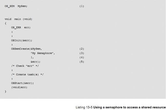
L13-5��1������һ���ź������ź������������ͱ����� OS_SEM��
L13-5(1) The application must declare a semaphore
as a variable of type OS_SEM. This variable will be referenced by other
semaphore services.
L13-5��2��ͨ������ OSSemCreate()����һ���ź��������ź�����ַ���ݸ������ĵ�һ���������ź��������ڴ�������ܱ���������ʹ�á�������ź������� main()�����б������ģ�Ҳ�����������б�������
L13-5(2) Create a semaphore by calling
OSSemCreate() and pass the address to the semaphore allocated in (1). The
semaphore must be created before it can be used by other tasks. Here, the
semaphore is initialized in startup code (i.e., main ()), however it could also
be initialized by a task (but it must be initialized before it is used).
L13-5��3��Ϊ�ź�������һ�����֣�����ʱ�ͺ�����ʶ�����ֿ��Դ洢�� ROM����Ϊ ROM �Ŀռ�Զ���� RAM�������Ҫ�ڳ�������ʱ�ı��ź��������֣����������������ʽ���� RAM �У������������ַ�� OSSemCreate()����Ȼ������������Կ��ַ���ֹ��
L13-5(3) Assign an ASCII name to the semaphore,
which can be used by debuggers or ��C/Probe to easily identify the semaphore.
Storage for the ASCII characters is typically in ROM, which is typically more
plentiful than RAM. If it is necessary to change the name of the semaphore at
runtime, store the characters in an array in RAM and simply pass the address of
the array to OSSemCreate(). Of course, the array must be NUL terminated.
L13-5��4�������ź�������ֵ����������Դֻ���б�һ������ռ��ʱ�����ź�������ֵΪ 1.
L13-5(4) Specify the initial value of the
semaphore. Initialize the semaphore to 1 when the semaphore is used to access a
single shared resource (as in this example).
L13-5��5�������ź����Ĵ������ OSSemCreate()����һ��������š�
������еIJ���������Ч�ģ��������Ϊ OS_ERR_NONE��
L13-5(5) OSSemCreate() returns an error code based
on the outcome of the call. If all the arguments are valid, err will contain
OS_ERR_NONE. Refer to the description of OSSemCreate() in Appendix A,
����C/OS-III API Reference Manual�� on page 375 for a list of other error codes
and their meaning.
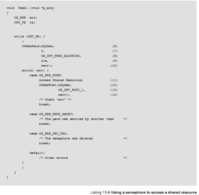
L13-6��6��ͨ������ OSSemPend()�����ȴ�һ���ź������������ָ�����ȴ����ź�����������ź���֮ǰ�Ѿ���������
L13-6(6) The task pends (or waits) on the
semaphore by calling OSSemPend(). The application must specify the desired
semaphore to wait upon, and the semaphore must have been previously created.
L13-6��7����������ǵȴ��ź���������ֵ����ʱ��Ϊ��С��λ����ʵ�ϣ��ȴ���������ʱ��Ƶ�ʡ���ʱ��Ƶ��Ϊ 1000Hz ʱ��10 ��ʱ�������ȴ�ʱ���� 10 ���롣��������ֵΪ 0 ��ζ������һֱ�ȴ����ź�����
L13-6(7) The next argument is a timeout specified
in number of clock ticks. The actual timeout depends on the tick rate. If the
tick rate (see OS_CFG_APP.H) is set to 1000, a timeout of 10 ticks represents
10 milliseconds. Specifying a timeout of zero (0) means waiting forever for the
semaphore.
L13-6
�� 8 �����������������˹���ķ�ʽ�������ַ�ʽ��
OS_OPT_PEND_BLOCKING �� OS_OPT_PEND_NON_BLOCKING����һ�ַ�ʽ���еȴ��������ź�����Чʱ������ OSSemPend()������ᱻ����ֱ�����յ��ź������������ڶ��ַ�ʽ���ȴ��������ź�����Чʱ������ OSSemPend()���Ѹ�ٷ��أ��������𣩡�
��ʹ���ź�������������Դʱ�ڶ��ַ�ʽ���ٱ��õ���
L13-6(8) The third argument specifies how to wait.
There are two options: OS_OPT_PEND_BLOCKING and OS_OPT_PEND_NON_BLOCKING. The
blocking option means that if the semaphore is not available, the task calling
OSSemPend() will wait until the semaphore is posted or until the timeout
expires. The non-blocking option indicates that if the semaphore is not
available, OSSemPend() will return immediately and not wait. This last option
is rarely used when using a semaphore to protect a shared resource.
L13-6��9���ź������ύʱ�� uC/OS-III ��ȡ��ǰʱ���������
OSSemPend()����ʱ�������ʱ�����������ܿ������û�֪���ź�����ʲôʱ���ύ�ġ�������յ��ź������� OS_TS_GET() ��ȡ��ǰ��ʱ����������ֵ����֪���ȴ�ʱ����
{�ź������ύ��������յ��ź������ȴ���ʱ��}��
L13-6(9) When the semaphore is posted, ��C/OS-III
reads a ��timestamp�� and returns this timestamp when OSSemPend() returns. This
feature allows the application to know ��when�� the post happened and the
semaphore was released. At this point, OS_TS_GET() is read to get the current
timestamp and compute the difference, indicating the length of the wait.
L13-6��10�������ź����Ĵ������ OSSemPend()����һ��������š�����ź��������ɹ����������Ϊ OS_ERR_NONE���������ʧ�ܣ�������Ż���������ԭ���������ֵ�Ǻ��б�Ҫ�ģ���Ϊ�����������ɾ��������ź�����ȡ���������Ĺ���״̬��Ȼ�����ڳ�������ʱ���Ƽ�ɾ���ں˶�����Ϊ����ܻᵼ�����صĺ����
L13-6(10) OSSemPend() returns an error code based on the outcome
of the call. If the call is successful, err will contain OS_ERR_NONE. If not,
the error code will indicate the reason for the error. See Appendix A,
����C/OS-III API Reference Manual�� on page 375 for a list of possible error code
for OSSemPend(). Checking for error return values is important since other
tasks might delete or otherwise abort the pend. However, it is not a
recommended practice to delete kernel objects at run time as the action may
cause serious problems.
L13-6��11���� OSSemPend()��ȷ����ʱ������Ϳ��Է������������Դ��
L13-6(11) The resource can be accessed when OSSemPend()
returns, if there are no errors.
L13-6��12����Դ���ʽ������������ OSSemPost()�ͷ�����ź�����
L13-6(12) When finished accessing the resource, simply
call OSSemPost() and specify the semaphore to be released.
L13-6��13��OS_OPT_POST_1 ��ζ������ź���ֻ�ܱ���������ռ�á�
L13-6(13) OS_OPT_POST_1 indicates that the semaphore is
signaling a single task, if there are many tasks waiting on the semaphore. In
fact, always specify this option when a semaphore is used to access a shared
resource.
L13-7��14�������� uC/OS-III ����һ�����õ�ַ��Ӧ�ı����д�ź������صĴ�����š�
L13-6(14) As with most ��C/OS-III functions, specify the
address of a variable that will receive an error message from the call.
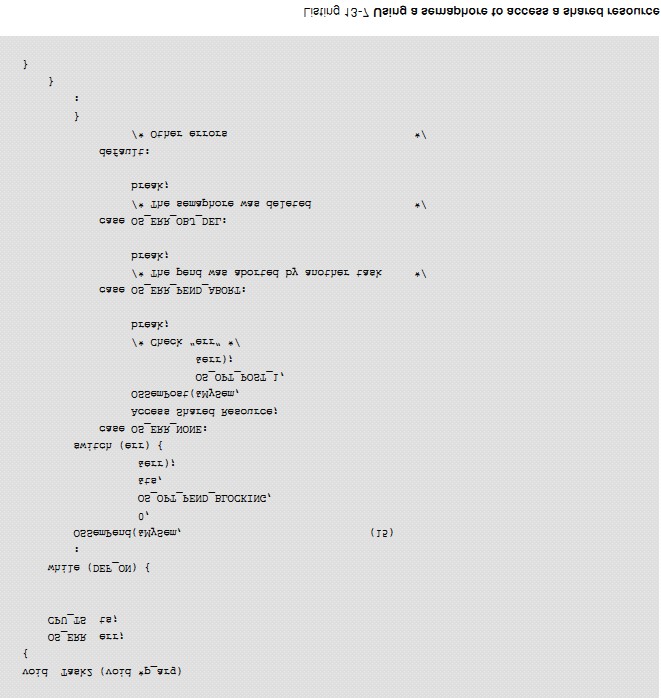
L13-7��15������Ҫ���ʹ�����Դ������ҲҪ����ͬ���IJ��衣
L13-7(15)
Another task wanting to access the shared resource needs to use the same
procedure to access the shared resource.
�����ڹ��� I/O ʱ���ź����dz����á�����һ�������������ͬ���ַ�����ӡ������ӡ�������ش�ӡ������������ַ������磬����һ��Ҫ��ӡ"I am Taks 1"���������Ҫ��ӡ"I am Task
2"����ô����Ϳ���Ϊ"I Ia amm TTasask k1 2"��
Semaphores
are especially useful when tasks share I/O devices. Imagine what would happen
if two tasks were allowed to send characters to a printer at the same time. The
printer would contain interleaved data from each task. For instance, the
printout from Task 1 printing ��I am Task 1,�� and Task 2 printing ��I am Task 2,��
could result in ��I Ia amm T Tasask k1 2��.
����������£��������ź��������ź�������ֵ��Ϊ 1����ֵ�ź������������Ǽģ��ڷ��ʴ�ӡ��֮ǰ��������Ȼ�ø��ź�������ͼ 13-1
��ʾ�������������������ռ�ʴ�ӡ��������һ�������ڷ��ʴ�ӡ��֮ǰ������Կ�ף��ź����������Կ�ס�
In
this case, use a semaphore and initialize it to 1 (i.e., a binary semaphore).
The rule is simple: to access the printer each task must first obtain the
resource��s semaphore. Figure 13-1 shows tasks competing for a semaphore to gain
exclusive access to the printer. Note that a key, indicating that each task
must obtain this key to use the printer, represents the semaphore symbolically.
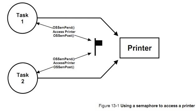
�������ӱ�����������ö�Ӧ���ź������ܷ�����Դ������һ���ܱ����ٽ�κܺõķ����������ù�����Դǰ�����Ȼ���ź��������磬һ�� RS-232C �˿ڱ�������������������Ŀ��������������Ӧ����ͼ 13-2 ��ʾ
The
above example implies that each task knows about the existence of the semaphore
to access the resource. It is almost always better to encapsulate the critical
section and its protection mechanism. Each task would therefore not know that
it is acquiring a semaphore when accessing the resource. For example, an
RS-232C port is used by multiple tasks to send commands and receive responses
from a device connected at the other end as shown in Figure 13-2.
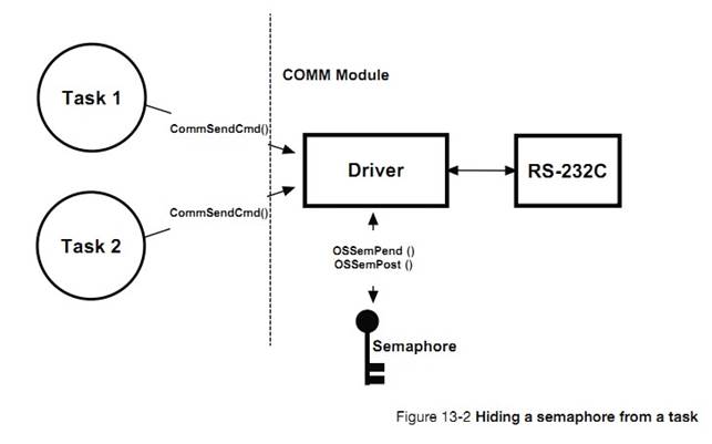
����CommSendCmd()�����ã��������������������ַ�����ָ����Ӧ�ַ�����ָ�롢ʱ�����ޣ��ڹ涨ʱ���ڿ���û����Ӧ�������������α�������б� 13-8
The
function CommSendCmd() is called with three arguments: the ASCII string
containing the command, a pointer to the response string from the device, and
finally, a timeout in case the device does not respond within a certain amount
of time. The pseudo-code for this function is shown in Listing 13-8
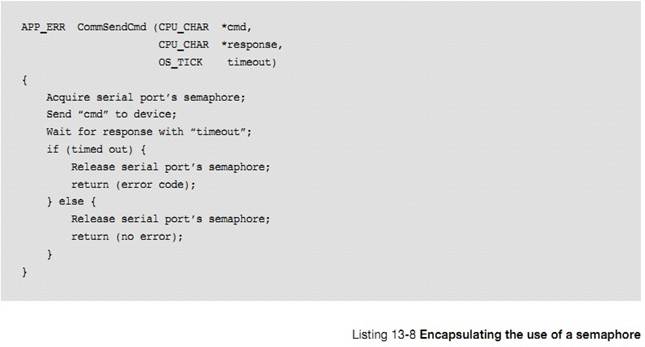
ÿ���������������������ܷ��������RS-232C�˿ڡ��ٶ�����ź�������ֵ�Ѿ�������Ϊ 1��ͨ���������ij�ʼ������������һ���������CommSendCmd()����ź���������������ȴ���Ӧ����ʱ�˿ڴ���æ״̬����ʱ�ڶ���������Ҫ���������ô�ڶ�������ͱ�����ֱ���ź������ͷš���һ�������ͷ��ź����ڶ����������ź���������������RS-232C�˿ڡ�
Each
task that needs to send a command to the device must call this function. The
semaphore is assumed to be initialized to 1 (i.e., available) by the
communication driver initialization routine. The first task that calls
CommSendCmd() acquires the semaphore, proceeds to send the command, and waits
for a response. If another task attempts to send a command while the port is
busy, this second task is suspended until the semaphore is released. The second
task appears simply to have made a call to a normal function that will not
return until the function performs its duty. When the semaphore is released by
the first task, the second task acquires the semaphore and is allowed to use
the RS-232C port.
13-3-2 �ź�������ֵ
��������Դͬʱ���Ա�����������ʱ���ź�������ֵ���ڱ�ǹ�����Դ��ͬʱ�����ٸ�������ʡ����磬����ؿ��Ա��������ͬʱ���ʣ���ͼ 13-3���ٶ�������ж����� 10 ��������������ͨ������ BufReq()���һ��������������ͨ������ BufRel()�ͷ�һ����������α�������б� 13-9 ��ʾ��
A
counting semaphore is used when elements of a resource can be used by more than
one task at the same time. For example, a counting semaphore is used in the
management of a buffer pool, as shown in Figure 13-3. Assume that the buffer
pool initially contains 10 buffers. A task obtains a buffer from the buffer
manager by calling BufReq(). When the buffer is no longer needed, the task
returns the buffer to the buffer manager by calling BufRel(). The pseudo-code
for these functions is shown in Listing 13-9.
��������� 10 ���������ռ��һ���������������ź�������ֵ����ʼ��Ϊ 10�������еĻ������������꣬���������뻺����ʱ�ᱻ����ֱ���ź������ͷš�
The
buffer manager satisfies the first 10 buffer requests because the semaphore is
initialized to 10. When all buffers are used, a task requesting a buffer is
suspended until a buffer becomes available. Use ��C/OS-III��s OSMemGet() and
OSMemPut() (see Chapter 17, ��Memory Management�� on page 323) to obtain a buffer
from the buffer pool.
��������ɶԻ�������ʹ�ú���� BufRel() �ͷŻ�����������������������������ȴ�����������ֱ�ӽ��˻����������������û������ȴ�����������������������뵽���������У������ź�������ֵ������ͨ���������������Ľӿ� BufReq() �� BufRel()�������߲����˽�����ʵ��ϸ�ڡ�
When
a task is finished with the buffer it acquired, the task calls BufRel() to
return the buffer to the buffer manager and the buffer is inserted into the
linked list before the semaphore is signaled. By encapsulating the interface to
the buffer manager in BufReq() and BufRel(), the caller does not need to be
concerned with actual implementation details.
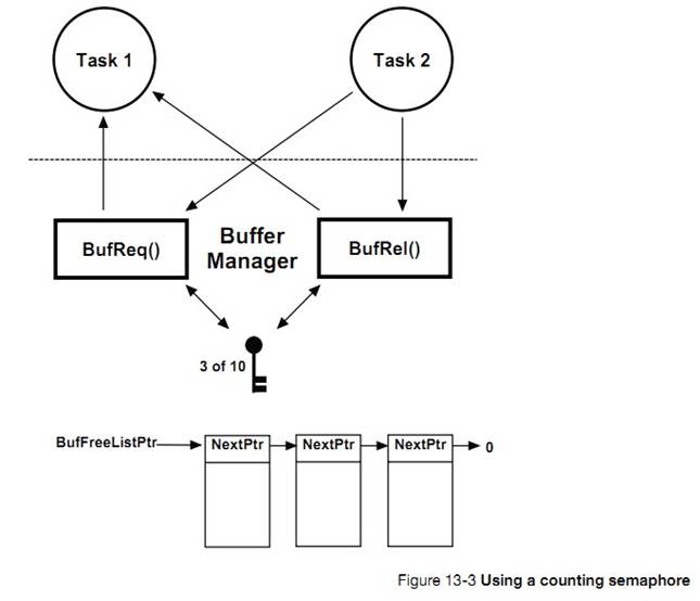
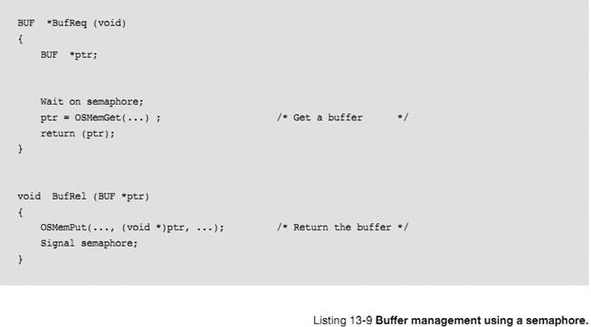
13-3-3 �ź�����ע�������
���ź������ʹ�����Դ���ᵼ���ж��ӳ١���������ִ���ź����������Ĺ�����Դʱ��ISR ������ȼ����������ռ������
Using
a semaphore to access a shared resource does not increase interrupt latency. If
an ISR or the current task makes a higher priority task ready to run while
accessing shared data, the higher priority task executes immediately.
Ӧ���п�����������ź������ڱ���������Դ��Ȼ�����Ƽ����ź������� I/O �˿ڵı������������ڴ��ַ��
An
application may have as many semaphores as required to protect a variety of different
resources. For example, one semaphore may be used to access a shared display,
another to access a shared printer, another for shared data structures, and
another to protect a pool of buffers, etc. However, it is preferable to use
semaphores to protect access to I/O devices rather than memory locations.
�ź�������������ʹ�á��ܶ�����£�����һ����̵Ĺ�����Դʱ���Ƽ�ʹ���ź�����������ͷ��ź��������� CPU ʱ�䡣ͨ����/ ���ж��ܸ���Ч��ִ����Щ������
Semaphores
are often overused. The use of a semaphore to access a simple shared variable
is overkill in most situations. The overhead involved in acquiring and
releasing the semaphore consumes valuable CPU time. Perform the job more
efficiently by disabling and enabling interrupts, however there is an indirect
cost to disabling interrupts: even higher priority tasks that do not share the
specific resource are blocked from using the CPU.
Ϊ��˵������������������һ��32 λ��������������һ������������������� 1���ڶ�����������������㡣���ǵ�ִ����Щ������ʱ�̣ܶ�����Ҫʹ���ź�����ִ���������ǰ����ֻ����жϣ�ִ����Ϻ��ٿ��жϡ������������������Ҵ�������֧��Ӳ���������ʱ������Ҫ�õ��ź�������Ϊ����������´���������������ϳ�ʱ�䡣
Suppose,
for instance, that two tasks share a 32-bit integer variable. The first task
increments the variable, while the second task clears it. When considering how
long a processor takes to perform either operation, it is easy to see that a
semaphore is not required to gain exclusive access to the variable. Each task
simply needs to disable interrupts before performing its operation on the
variable and enable interrupts when the operation is complete. A semaphore
should be used if the variable is a floating-point variable and the microprocessor
does not support hardware floating-point operations. In this case, the time
involved in processing the floating-point variable may affect interrupt latency
if interrupts are disabled.
�ź����ᵼ��һ�����ص����⣺���ȼ���ת��
Semaphores
are subject to a serious problem in real-time systems called priority
inversion, which is described in section 13-3-5 ��Priority Inversions�� on page
232.
13-3-4 �ź����Ľṹ
����ǰ���ᵽ�ģ��ź������ں˶���ͨ���������� OS_SEM ���壬OS_SEM Դ�ڽṹ�� os_sem(�� OS.H)�����
13-10 ��ʾ��
As
previously mentioned, a semaphore is a kernel object as defined by the OS_SEM
data type, which is derived from the structure os_sem (see OS.H) as shown in
Listing 13-10.
uC/OS-III
�����ź�����صĴ��붼������ OS_SEM.C �С�ͨ������
OS_CFG.H �е� OS_CFG_SEM_EN Ϊ 1 ʹ���ź�����
The
services provided by ��C/OS-III to manage semaphores are implemented in the file
OS_SEM.C. ��C/OS-III licensees have access to the source code. In this case,
semaphore services are enabled at compile time by setting the configuration
constant OS_CFG_SEM_EN to 1 in OS_CFG.H.
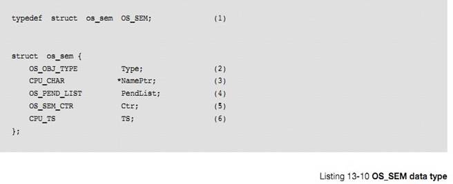
L13-10��1���� uC/OS-III �У����еĽṹ�嶼���ض����������ͣ��ԡ�OS_����ͷ����ȫ����д��
L13-10(1) In ��C/OS-III, all structures are given a data
type. All data types start with ��OS_�� and are uppercase. When a semaphore is
declared, simply use OS_SEM as the data type of the variable used to declare
the semaphore.
L13-10��2������ṹ��ĵ�һ�������ǡ�Type������ uC/OS-III ʶ�����������һ���ź������������ں˶���Ҳ�С�Type������Ϊ�ṹ��ĵ�һ���������������Ҫ����һ���ں˶���uC/OS-III ���������õ��ں˶�������������Ƿ��Ӧ�����磬�����Ҫ����һ����Ϣ���� OS_Q ����������ʵ�ʴ��ݵ���һ���ź��� OS_SEM�� uC/OS-III �ͻ��������һ����Ч�IJ����������ش�����š�
L13-10(2) The structure starts with a ��Type�� field, which
allows it to be recognized by ��C/OS-III as a semaphore. Other kernel objects
will also have a ��.Type�� as the first member of the structure. If a function is
passed a kernel object, ��C/OS-III will confirm that it is being passed the
proper data type. For example, if passing a message queue (OS_Q) to a semaphore
service (for example OSSemPend()), ��C/OS-III will recognize that an invalid
object was passed, and return an error code accordingly.
L13-10��3��ÿ���ں˶����Ա�����һ�����֣������� ASCII �ַ�����ɣ��������Կ��ַ���β��
L13-10(3) Each kernel object can be given a name for
easier recognition by debuggers or ��C/Probe. This member is simply a pointer to
an ASCII string, which is assumed to be NUL terminated.
L13-10��4�����ж������ȴ��ź������ź����ͻὫ��Щ����������������С������½� 10��������С���
L13-10(4) Since it is possible for multiple tasks to wait
(or pend) on a semaphore, the semaphore object contains a pend list as
described in Chapter 10, ��Pend Lists (or Wait Lists)�� on page 177.
L13-10��5���ź����а���һ���ź���������ֵ���ź�������ֵ���Զ���Ϊ 8 λ��16 λ���� 32 λ��ȡ����
OS_TYPE.H �е� OS_SEM_CTR ����α�����ġ�
L13-10(5) A semaphore contains a counter. As explained
above, the counter can be implemented as either an 8-, 16- or 32-bit value,
depending on how the data type OS_SEM_CTR is declared in OS_TYPE.H.
uC/OS-III
�ж�ֵ�ź����Ͷ�ֵ�ź����Ķ�����һ���ġ�ֻ���ź��������������������������ź���ʱ���ź�������ֵ����ʼ��Ϊ
1����ô�����Ƕ�ֵ�ź�������������ź���ʱ���ź�������ֵ��ʼ������ 1����ô�����Ƕ�ֵ�ź�����
��C/OS-III
does not make a distinction between binary and counting semaphores. The distinction
is made when the semaphore is created. If creating a semaphore with an initial
value of 1, it is a binary semaphore. When creating a semaphore with a value
> 1, it is a counting semaphore. In the next chapter, we discover that a
semaphore is more often used as a signaling mechanism and therefore, the
semaphore counter is initialized to zero.
L13-10��6���ź����а�����һ��ʱ����������洢����һ���ź������ύʱ��ʱ��������ź������ύʱ��CPU
��ʱ�������ȡ�������ź�����ʱ��������У��� OSSemPend()������ʱ���ܶ�ȡ���ʱ���������
L13-10(6) A semaphore contains a timestamp used to indicate
the last time the semaphore was posted. ��C/OS-III assumes the presence of a
free-running counter that allows the application to make time measurements.
When the semaphore is posted, the free-running counter is read and the value is
placed in this field, which is returned when OSSemPend() is called. The value
of this field is more useful when a semaphore is used as a signaling mechanism
(see Chapter 14, ��Synchronization�� on page 251), as opposed to a
resource-sharing mechanism.
��ʹ�û��˽� OS_SEM ����ɣ��û�����Ҳ����ֱ�ӷ����ź����еı���������ͨ��
uC/OS-III �ṩ�� API��
Even
if the user understands the internals of the OS_SEM data type, the application
code should never access any of the fields in this data structure directly.
Instead, always use the APIs provided with ��C/OS-III.
�ź�����ʹ��֮ǰ���뱻������
As
previously mentioned, semaphores must be created before they can be used by an
application.
�ڷ��ʹ�����Դ֮ǰ�������ͨ�� OSSemPend()�������ź��������б� 13-11 ��ʾ
A
task waits on a semaphore before accessing a shared resource by calling
OSSemPend() as shown in Listing 13-11 (see Appendix A, ����C/OS-III API Reference
Manual�� on page 375 for details regarding the arguments).
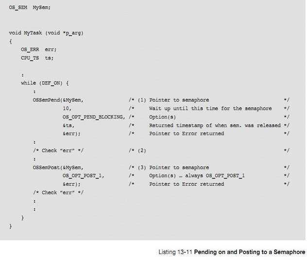
L13-11��1������ OSSemPend()���ú��������ȼ��ݸ����IJ����Ƿ���Ч��
����ź�������ֵ���� 0��OS_SEM.Ctr������������Ч���ź�������ֵ�ᱻ�ݼ������� OSSemPend()���ء�����Ϳ���ռ�øù�����Դ��
L13-11(1)
When called, OSSemPend() starts by checking the arguments passed to this
function to make sure they have valid values.
If
the semaphore counter (.Ctr of OS_SEM) is greater than zero, the counter is
decremented and OSSemPend() returns. If OSSemPend() returns without error, then
the task now owns the shared resource.
���ѡ���� OS_OPT_PEND_NON_BLOCKING ģʽ�����ź�����Чʱ
OSSemPend()Ѹ�ٷ��ش�����š����ѡ���� OS_OPT_PEND_BLOCKING ģʽ���ź�����Чʱ����ᱻ������ź����Ĺ�������У����������ȼ��������ȼ��������ڶ������ײ���
When
the semaphore counter is zero, this indicates that another task owns the
semaphore, and the calling task may need to wait for the semaphore to be
released. If specifying OS_OPT_PEND_NON_BLOCKING as the option (the application
does not want the task to block), OSSemPend() returns immediately to the caller
and the returned error code indicates that the semaphore is unavailable. Use
this option if the task does not want to wait for the resource to be available,
and would prefer to do something else and check back later.
If
specifying the OS_OPT_PEND_BLOCKING option, the calling task will be inserted
in the list of tasks waiting for the semaphore to become available. The task is
inserted in the list by priority order and therefore, the highest priority task
waiting on the semaphore is at the beginning of the list.
��������˷� 0 �ĵȴ����ޣ�������Ҳ�ᱻ���뵽ʱ�������У��ȴ�����Ϊ 0 ��ζ��Ҫ��Զ�صȴ���ȥֱ���ź������ͷš����������£��������ĵȴ�ʱ�䡣���õȴ������Խ�����������⣬�����Ӧ�ü��з�ֹ��������Ҫ��ͬһʱ��ռ�ö���ź������ö��ˡ�
If
specifying a non-zero timeout, the task will also be inserted in the tick list.
A zero value for a timeout indicates that the user is willing to wait forever
for the semaphore to be released. Most of the time, specify an infinite timeout
when using the semaphore in resource sharing. Adding a timeout may temporarily
break a deadlock, however, there are better ways of preventing deadlock at the
application level (e.g., never hold more than one semaphore at the same time;
resource ordering; etc.).
The
scheduler is called since the current task is no longer able to run (it is
waiting for the semaphore to be released). The scheduler will then run the next
highest-priority task that is ready to run.
When
the semaphore is released and the task that called OSSemPend() is again the
highest-priority task, ��C/OS-III examines the task status to determine the
reason why OSSemPend() is returning to its caller.
OSSemPend()���ص�ԭ��
The
possibilities are:
1.������ź���
1.The
semaphore was given to the waiting task
2.��������ȡ���˸�����Ĺ���
2��The pend was aborted by another task
3.�ȴ���ʱ
3��The semaphore was not posted within the specified timeout
4.�ź�����ɾ��
4) The semaphore was deleted
OSSemPend()�ķ��ش��Ű�����Щ��Ϣ��
When
OSSemPend() returns, the caller is notified of the above outcome through an
appropriate error code.
L13��11��2����� OSSemPend()���صĴ�����ţ���Ϊ OS_ERR_NONE ���ʾ����������ź�����
L13-11(2) If OSSemPend() returns with err set to OS_ERR_NONE,
assume that you now have access to the resource.
L13-11��3������Թ�����Դ������Ϻ������ OSSemPost()�ͷ�����ź�����ͬ���ģ�OSSemPost()����ݸ����IJ����Ƿ���Ч��
L13-11(2) If OSSemPend() returns with err set to OS_ERR_NONE,
assume that you now have access to the resource.
Ȼ�� OSSemPost()���� OS_TS_GET()��õ�ǰ��ʱ��������������ź����еı����С��ټ���Ƿ�����������ȴ�����ź�����
If
err contains anything else, OSSemPend() either timed out (if the timeout
argument was non-zero), the pend was aborted by another task, or the semaphore
was deleted by another task. It is always important to examine the returned
error code and not assume that everything went well.
L13-11(3) When the task is finished accessing the
resource, it needs to call OSSemPost() and specify the same semaphore. Again,
OSSemPost() starts by checking the arguments passed to this function to make
sure there are valid values.
OSSemPost()
then calls OS_TS_GET() to obtain the current timestamp so it can place that
information in the semaphore to be used by OSSemPend().
OSSemPost()
checks to see if any tasks are waiting for the semaphore. If not, OSSemPost()
simply increments p_sem->Ctr, saves the timestamp in the semaphore, and
returns.
If
there are tasks waiting for the semaphore to be released, OSSemPost() extracts
the highest-priority task waiting for the semaphore. This is a fast operation
as the pend list is sorted by priority order.
When
calling OSSemPost(), it is possible to specify as an option to not call the
scheduler. This means that the post is performed, but the scheduler is not
called even if a higher priority task waits for the semaphore to be released.
This allows the calling task to perform other post functions (if needed) and
make all posts take effect simultaneously without the possibility of context
switching in between each post.
13-3-5 ���ȼ���ת
���ȼ���ת��ʵʱϵͳ�е�һ���������⣬�������ڻ������ȼ�����ռʽ�ں��С�ͼ 13-4 ��ʾ��һ�����ȼ���ת����������� H �����ȼ��������� M������ M �����ȼ��������� L��
Priority
inversion is a problem in real-time systems, and occurs only when using a
priority-based preemptive kernel. Figure 13-4 illustrates a priority-inversion
scenario. Task H (high priority) has a higher priority than Task M (medium
priority), which in turn has a higher priority than Task L (low priority).
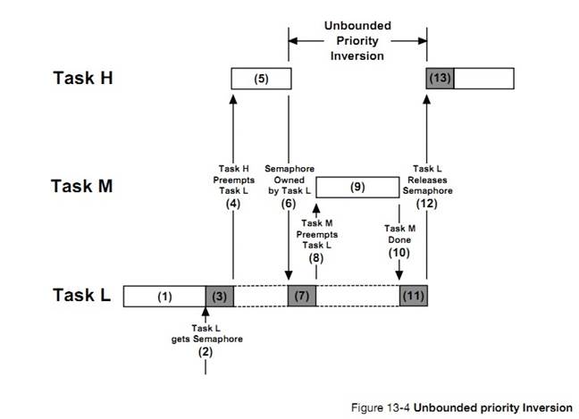
F13-4��1������ H��High ���ȼ��������� M��Medium ���ȼ������ڵȴ��¼����������� L��Low ���ȼ������ڱ����С�
F13-4(1) Task H and Task M are both waiting for an
event to occur and Task L is executing.
F13-4��2����ʱ������ L �������ź�����
F13-4(2) At some point, Task L acquires a
semaphore, which it needs before it can access a shared resource.
F13-4��3������ L ���ʹ�����Դ��
F13-4(3) Task L performs operations on the
acquired resource.
F13-4��4������ H ���ȴ����¼�������uC/OS-III
�������� L��
F13-4(4) The event that Task H was waiting for
occurs, and the kernel suspends Task L and start executing Task H since Task H
has a higher priority.
F13-4��5����ʼִ������ H��
F13-4(5) Task H performs computations based on the
event it just received.
F13-4��6���������� H ��Ҫ�������� L ��ռ�õĹ�����Դ����ʱ�ù�����Դ������ L ռ�ã�����Ϊ����Դ������ L ռ�ã����� H �������������еȴ�����ź������ͷš�
F13-4(6) Task H now wants to access the resource
that Task L currently owns (i.e., it attempts to get the semaphore that Task L
owns). Because Task L owns the resource, Task H is placed in a list of tasks
waiting for the semaphore to be free.
F13-4��7������ L ���ָ�������ִ�С�
F13-4(7) Task L is resumed and continues to access
the shared resource.
F13-4��8������ L ������ M ��ռ��Ϊ���� M ���ȴ����¼�������
F13-4(8) Task L is preempted by Task M since the event
that Task M was waiting for occurred.
F13-4��9������ M ��ʼִ�С�
F13-4(9) Task M handles the event.
F13-4��10������ M ִ����ϣ�uC/OS-III
�� CPU ����Ȩ����������L��
F13-4(10) When Task M completes, the kernel relinquishes
the CPU back to Task L.
F13-4��11������ L ��ִ�С�
F13-4(11) Task L continues accessing the resource.
F13-4��12������ L ִ����ϲ��ͷ���Դ����ʱ������ H ��ø���Դ��uC/OS-III�������л������� H��
F13-4(12) Task L finally finishes working with the resource
and releases the semaphore. At this point, the kernel knows that a
higher-priority task is waiting for the semaphore, and a context switch takes
place to resume Task H.
F13-4��13������ H ��ʼִ�С�
F13-4(13)Task
H has the semaphore and can access the shared resource.
���Կ��������� H ������ L ��ִ�У���Ϊ���� H
�ȴ����� L��ռ�õ���Դ���鷳�������� M ��ռ���� L�������� M ��Ҫִ�кܳ�ʱ�䣬������ H �ᱻ�ӳٺܳ�ʱ���ִ�У���������ȼ���ת��
So,
what happened here is that the priority of Task H has been reduced to that of
Task L since it waited for the resource that Task L owned. The trouble begins
when Task M preempted Task L, further delaying the execution of Task H. This is
called an unbounded priority inversion. It is unbounded because any medium
priority can extend the time Task H has to wait for the resource. Technically,
if all medium-priority tasks have known worst-case periodic behavior and
bounded execution times, the priority inversion time is computable. This
process, however, may be tedious and would need to be revised every time the
medium priority tasks change.
����ͨ���������� L �����ȼ�����������⣨ֻ�ڸ�������ʹ�����Դʱ�������ʽ�����ͻָ���������ȼ������� L �����ȼ���Ҫ������������ H �����ȼ���
This
situation can be corrected by raising the priority of Task L, only during the
time it takes to access the resource, and restore the original priority level
when the task is finished. The priority of Task L should be raised up to the
priority of Task H. ��C/OS-III contains a special type of semaphore that does
just that called a mutual-exclusion semaphore.
uC/OS-III
֧��һ���������͵Ķ�ֵ�ź������� mutex�����ڽ�����ȼ���ת���⡣ͼ 13-5 ��ʾ�����ȼ����������ͨ�� mutex ����ġ�
��C/OS-III
supports a special type of binary semaphore called a mutual exclusion semaphore
(also known as a mutex) that eliminates unbounded priority inversions.Figure
13-5 shows how priority inversions are bounded using a Mutex.
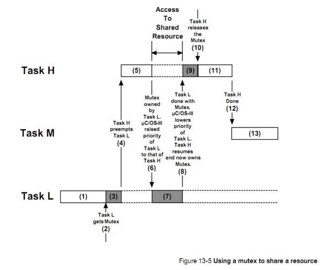
F13-5��1������ H ������ M �ȴ��¼��ķ��������� L ��ִ�С�
F13-5(1) Task H and Task M are both waiting for an
event to occur and Task L is executing.
F13-5��2����ʱ������ L ���벢���һ��
mutex��
F13-5(2) At some point, Task L acquires a mutex,
which it needs before it is able to access a shared resource.
F13-5��3������ L ��ִ�С�
F13-5(3) Task L performs operations on the
acquired resource.
F13-5��4������ H ������ M ���ȴ����¼����������� L ����ռ��
F13-5(4) The event that Task H waited for occurs
and the kernel suspends Task L and begins executing Task H since Task H has a
higher priority.
F13-5��5������ H ��ʼִ�С�
F13-5(5) Task H performs computations based on the
event it just received.
F13-5��6������ H ��Ҫ�������� L ռ�õĹ�����Դ�����ǵ����� L ռ�������Դ��uC/OS-III �������� L �����ȼ������� H ��ͬ�������ͷ�ֹ������ L ������ M ��ռ�����е����ȼ���������ռ����
F13-5(6) Task H now wants to access the resource
that Task L currently owns (i.e., it attempts to get the mutex from Task L).
Given that Task L owns the resource, ��C/OS-III raises the priority of Task L to
the same priority as Task H to allow Task L to finish with the resource and
prevent Task L from being preempted by medium-priority tasks.
F13-5��7������ L �������������Դ������������ L �����ȼ��������� H �����ȼ���ע��������� H ��������Ϊ��Ҫ�ȴ����� L �ͷ�
mutex�����仰˵������ H �����뵽 mutex �Ĺ�������С�
F13-5(7) Task L continues accessing the resource,
however it now does so while it is running at the same priority as Task H. Note
that Task H is not actually running since it is waiting for Task L to release
the mutex. In other words, Task H is in the mutex wait list.
F13-5��8������ L �Թ�����Դ�ķ���ִ����ϲ��ͷ� mutex��uC/OS-III �ָ����� L ��ԭ�е����ȼ���Ȼ�� uC/OS-III ����� mutex �������� H��{���������� L �Ѿ�ȫ��ִ����ϣ����ǵ����ͷ��ź���ʱ�ͻᷢ�����ȶ�ת�������ȼ�����}
F13-5(8) Task L finishes working with the resource
and releases the mutex. ��C/OS-III notices that Task L was raised in priority
and thus lowers Task L to its original priority. After doing so, ��C/OS-III
gives the mutex to Task H, which was waiting for the mutex to be released.
F13-5��9������ H ��ʼִ�С�
F13-5(9) Task H now has the mutex and can access
the shared resource.
F13-5��10������ H �Թ�����Դ�ķ�����ϣ����ͷ���� mutex��
F13-5(10) Task H is finished accessing the shared
resource, and frees up the mutex.
F13-5��11������ H ����ִ�С�
F13-5(11) There are no higher-priority tasks to execute,
therefore Task H continues execution.
F13-5��12������ H ִ����ϡ�uC/OS-III
�� CPU ����Ȩ�������� M��
F13-5(12) Task H completes and decides to wait for an
event to occur. At this point, ��C/OS-III resumes Task M, which was made ready
to run while Task H or Task L were executing.
F13-5��13) ���� M ��ִ�С�
F13-5(13) Task M executes.
����û�����ȼ���ת�������ˡ���Ȼ������ L ռ�ù�����Դ��ʱ��Խ��Խ�á�
mutex
��һ���ں˶��������������� OS_MUTEX �����壬(OS_MUTEX
��ԭ���� os_mutex���� OS.H)��Ӧ���п���������� mutex�������ڴ������� RAM����ֻ������ſ���ʹ�� mutex��ISR ������ʹ��
mutex����
Note
that there is no priority inversion, only resource sharing. Of course, the
faster Task L accesses the shared resource and frees up the mutex, the better.
��C/OS-III
implements full-priority inheritance and therefore if a higher priority
requests the resource, the priority of the owner task will be raised to the
priority of the new requestor.
A
mutex is a kernel object defined by the OS_MUTEX data type, which is derived
from the structure os_mutex (see OS.H). An application may have an unlimited
number of mutexes (limited only by the RAM available).
Only
tasks are allowed to use mutual exclusion semaphores (ISRs are not allowed).
uC/OS-III
��������Ƕ��ռ�� mutex����������� mutex����ô������Ƕ������ mutex ��� 250 �Ρ���������Ҫ�ͷ���ͬ���������ͷŵ����mutex����һЩ����£�Ӧ���к���֪����������˶��ٴ� OSMutexPend()�����б� 13-12 ��ʾ
��C/OS-III
enables the user to nest ownership of mutexes. If a task owns a mutex, it can
own the same mutex up to 250 times. The owner must release the mutex an
equivalent number of times. In several cases, an application may not be
immediately aware that it called OSMutexPend() multiple times, especially if
the mutex is acquired again by calling a function as shown in Listing 13-12.
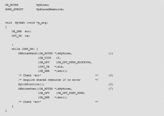
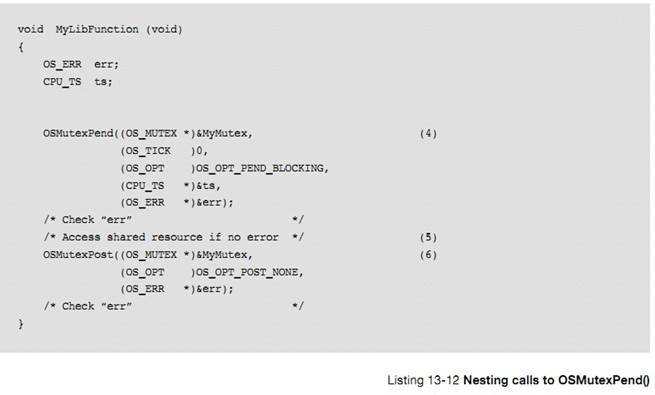
L13-12��1����������� mutex��OSMutexPend()����Ƕ����ֵΪ 1��
L13-12(1) A task starts by pending on a mutex to access
shared resources. OSMutexPend() sets a nesting counter to 1.
L13-12��2����ⷵ�صĴ�����ţ����û�д������� Mytask()ռ�ù�����Դ MySharedResource��
L13-12(2) Check the error return value. If no errors
exist, MyTask() owns MySharedResource.
L13-12��3������ MyLibFunction()�����н����ʹ�����Դ��
L13-12(3) A function is called that will perform
additional work.
L13-12��4������ MyLibFunction()�ڷ��ʹ�����Դǰ���� mutex����Ϊ��ǰ�Ѿ���� mutex������û��Ҫ�ٴλ�á����ǣ����� MyLibFunction()���ܱ���������Ҫ���ʹ�����Դ�ĺ������á�
uC/OS-III ����Ƕ�� mutex������MyLibFunction()�����ٴα����á�Ƕ����ֵ���ӵ� 2.
L13-12(4) The designer of MyLibFunction() knows that, to
access MySharedResource, it must acquire the mutex. Since the calling task
already owns the mutex, this operation should not be necessary. However,
MyLibFunction() could have been called by yet another function that might not
need access to MySharedResource. ��C/OS-III allows nested mutex pends, so this
is not a problem. The mutex nesting counter is thus incremented to 2.
L13-12��5��MyLibFunction()���ʹ�����Դ��
L13-12(5) MyLibFunction() can access the shared resource.
L13-12��6��mutex ���ͷţ�Ƕ����ֵ��Ϊ
1��OSMutexPost()���أ�
MyLibFunction()���ء�mutex ���DZ��������ռ�á�
L13-12(6)
The mutex is released and the nesting counter is decremented back to 1. Since
this indicates that the mutex is still owned by the same task, nothing further
needs to be done, and OSMutexPost() simply returns. MyLibFunction() returns to
its caller.
L13-12��7��mutex �ٴα��ͷţ���ʱ��Ƕ����ֵ��Ϊ 0������������Ի����� mutex��
L13-12(7)
The mutex is released again and, this time, the nesting counter is decremented
back to 0 indicating that other tasks can now acquire the mutex.
ͨ����� OSMutexPend()�ķ���ֵ��ȷ���Ѿ������ mutex����Ϊ����Щ����£�OSMutexPend()Ҳ�����ش�����ţ�mutex ��ɾ����������������� OSMutexPendAbort()ȡ���˶Ը� mutex �����롣
Always
check the return value of OSMutexPend() (and any kernel call) to ensure that
the function returned because you properly obtained the mutex, and not because
the return from OSMutexPend() was caused by the mutex being deleted, or because
another task called OSMutexPendAbort() on this mutex.
һ����ԣ��������ٽ���е��ú�����
As a
general rule, do not make function calls in critical sections.
�� 13-3 �г����� mutex ��صĺ�����Ȼ����������½��У�����ֻ�������������õ��ĺ��� OSMutexCreate()��OSMutexPend()�� OSMutexPost()�����������ڸ�¼ A �н��ܡ�
All
mutual exclusion semaphore calls should be in the leaf nodes of the source code
(e.g., in the low level drivers that actually touches real hardware or in other
reentrant function libraries).
There
are a number of operations that can be performed on a mutex, as summarized in
Table 13-3. However, in this chapter, we will only discuss the three functions
that most often used: OSMutexCreate(), OSMutexPend(), and OSMutexPost(). Other
functions are described in Appendix A, ����C/OS-III API Reference Manual�� on page
375.
�� 13-3 mutex �� API �ܽ�
|
������
|
����
|
|
OSMutexCreate()
|
����һ�� mutex
Create a mutex
|
|
OSMutexDle()
|
ɾ��һ�� mutex
Delete a mutex
|
|
OSMutexPend()
|
�ȴ�һ�� mutex
Wait on a mutex
|
|
OSMutexPendAbort()
|
����ȡ���ȴ� mutex
Abort the wait on a mutex
|
|
OSMutexPost()
|
�ͷ� mutex
Release a mutex
|
13-4-1 mutex ���ڲ�����
A
mutex is a kernel object defined by the OS_MUTEX data type, which is derived
from the structure os_mutex (see OS.H) as shown in Listing 13-13:
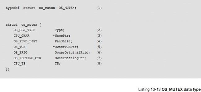
L13-13��1���� uC/OS-III �У����еĽṹ�嶼�ᱻ����һ���������͡����е�����������"OS_"��ͷ��ȫ����д������������ OS_MUTEX ���� mutex��
L13-13(1) In ��C/OS-III, all structures are given a data
type. All data types begin with ��OS_�� and are uppercase. When a mutex is
declared, simply use OS_MUTEX as the data type of the variable used to declare
the mutex.
L13-13��2���ṹ�忪ʼ��"Type"���� uC/OS-III ��ʶ������һ�� mutex��
L13-13(2) The structure starts with a ��Type�� field, which
allows it to be recognized by ��C/OS-III as a mutex. Other kernel objects may
also have a ��.Type�� as the first member of the structure. If a function is
passed a kernel object, ��C/OS-III will be able to confirm that it is being
passed the proper data type. For example, if passing a message queue (OS_Q) to
a mutex service (for example OSMutexPend()), ��C/OS-III will recognize that the
application passed an invalid object and return an error code accordingly.
L13-13��3��ÿ���ں˶�������һ�����֡�
L13-13(3) Each kernel object can be given a name to make
them easier to recognize by debuggers or ��C/Probe. This member is simply a
pointer to an ASCII string, which is assumed to be NUL terminated.
L13-13��4����Ϊ�����ж������ȴ���� mutex��mutex �а�����һ������������ڴ�ŵȴ��� mutex ������
L13-13(4) Because it is possible for multiple tasks to
wait (or pend on a mutex), the mutex object contains a pend list as described
in Chapter 10, ��Pend Lists (or Wait Lists)�� on page 177.
L13-13��5���������ռ����� mutex����ô�ñ���.OwnerTCBPtr ��ָ��ռ����� mutex ������� OS_TCB��
L13-13(5) If the mutex is owned by a task, it will point
to the OS_TCB of that task.
L13-13��6���������ռ����� mutex����ô�ñ��� OwnerOriginalPrio �д���������ԭ���ȼ�����ռ�� mutex ��������ȼ�������ʱ�ͻ��õ����������
L13-13(6) If the mutex is owned by a task, this field
contains the ��original�� priority of the task that owns the mutex. This field is
required in case the priority of the task must be raised to a higher priority
to prevent unbounded priority inversions.
L13-13��7��uC/OS-III ��������ռ��ͬ���� mutex ��� 250 �Ρ���Ҳ��Ҫ�ͷ���ͬ�������������ͷŵ���� mutex��
L13-13(7) ��C/OS-III allows a task to ��acquire�� the same
mutex multiple times. In order for the mutex to be released, the owner must
release the mutex the same number of times that it was acquired. Nesting can be
performed up to 250-levels deep.
L13-13��8��mutex �еı��� TS ���ڱ���� mutex ���һ�α��ͷŵ�ʱ������� mutex ���ͷţ���ȡʱ������ֵ����ŵ��ñ����С�
L13-13(8) A mutex contains a timestamp, used to indicate
the last time it was released. ��C/OS-III assumes the presence of a free-running
counter that allows applications to make time measurements. When the mutex is
released, the free-running counter is read and the value is placed in this
field, which is returned when OSMutexPend() returns.
�û����벻��ֱ�ӷ�������ṹ�塣����ͨ�� uC/OS-III �ṩ��API ���ʡ�
mutex
��ʹ��ǰ���뱻�������б� 13-14 ��ʾ����δ���һ��
mutex��
Application
code should never access any of the fields in this data structure directly.
Instead, always use the APIs provided with ��C/OS-III.
A
mutual exclusion semaphore (mutex) must be created before it can be used by an
application. Listing 13-14 shows how to create a mutex.
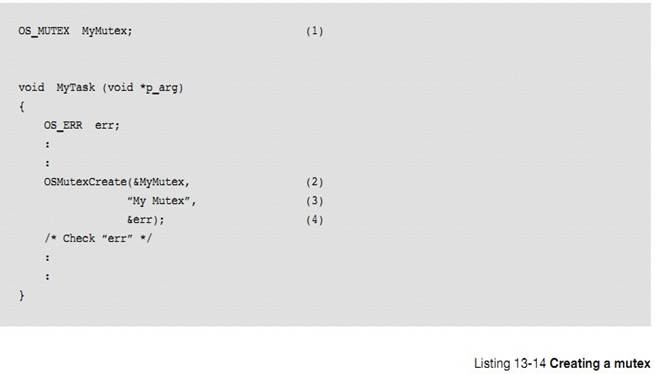
L13-14��1������һ�� OS_MUTEX ���͵ı�����
L13-14(1) The application must declare a variable of type
OS_MUTEX. This variable will be referenced by other mutex services.
L13-14��2������ OSMutexCreate()����һ�� mutex�����ݱ�����ַ���ú����ĵ�һ��������
L13-14(2) Create a mutex by calling OSMutexCreate() and
pass the address to the mutex allocated in (1).
L13-14��3������һ�����ָ� mutex��
L13-14(3) Assign an ASCII name to the mutex, which can be
used by debuggers or ��C/Probe to easily identify this mutex. There are no
practical limits to the length of the name since ��C/OS-III stores a pointer to
the ASCII string, and not to the actual characters that makes up the string.
L13-14��4��OSMutexCreate()���ڴ����Ľ������һ��������š�������������еIJ���������Ч�ģ���ô������Ž��� S_ERR_NONE��
L13-14(4) OSMutexCreate() returns an error code based on
the outcome of the call. If all the arguments are valid, err will contain
OS_ERR_NONE.
ע�⣺mutex �Ƕ�ֵ�ź���������û��Ҫ��ʼ������ֵ��
Note
that since a mutex is always a binary semaphore, there is no need to initialize
a mutex counter.
����ռ�ù�����Դǰ������ mutex��ͨ������ OSMutexPend()��������ź��������б� 13-15 ��ʾ
A
task waits on a mutual exclusion semaphore before accessing a shared resource
by calling OSMutexPend() as shown in Listing 13-15 (see Appendix A, ����C/OS-III
API Reference Manual�� on page 375 for details regarding the arguments).
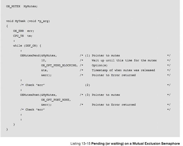
L13-15��1������ OSMutexPend()ʱ�ȼ��ݸ����IJ����ͷ���Ч��
L13-15(1)
When called, OSMutexPend() starts by checking the arguments passed to this
function to make sure they have valid values.
��� mutex ��Ч��OSMutexPend()�� mutex ��������������������OS_TCB ��ַ���� mutex ��ָ�� OwnerTCPPtr �У�������������ȼ�����mutex �ı��� OwnerOriginalPrio �У����� mutex ��Ƕ����ֵΪ 1��Ȼ��
OSMutexPend()���صĴ������Ϊ OS_ERR_NONE��
If
the mutex is available, OSMutexPend() assumes the calling task is now the owner
of the mutex and stores a pointer to the task��s OS_TCB in
p_mutex->OwnerTCPPtr, saves the priority of the task in
p_mutex->OwnerOriginalPrio, and sets a mutex nesting counter to 1.
OSMutexPend() then returns to its caller with an error code of OS_ERR_NONE.
����������Ѿ�ռ����� mutex��OSMutexPend()ֻ�Ǽؽ�Ƕ����ֵ�����������ش������ OS_ERR_MUTEX_OWNER��
If
the task that calls OSMutexPend() already owns the mutex, OSMutexPend() simply
increments a nesting counter. Applications can nest calls to OSMutexPend() up
to 250-levels deep. In this case, the error returned will indicate
OS_ERR_MUTEX_OWNER.
������������Ѿ�ռ����� mutex�����������"pend"����ʱΪ
OS_OPT_PEND_NON_BLOCKING
ģʽ��OSMutexPend()�������ش�����Ŷ�����������Ϊ������ȵ��� mutex ���ͷš�
If the mutex is already owned by
another task and OS_OPT_PEND_NON_BLOCKING is specified, OSMutexPend() returns
since the task is not willing to wait for the mutex to be released by its
owner.
��� mutex �ѱ��������ȼ�����ռ�ã�uC/OS-III �����������������ȼ������������ȼ���ͬ��
If
the mutex is owned by a lower-priority task, ��C/OS-III will raise the priority
of the owner to match the priority of the current task.
������������ȼ������Ѿ�ռ����� mutex�����������"pend"����ʱΪ OS_OPT_PEND_BLOCKING ģʽ��������ᱻ����������ֱ�� mutex
���ͷš������ڶ����и������ȼ�������������ȼ����ڶ��е��ײ���
If
specifying OS_OPT_PEND_BLOCKING as the option, the calling task will be
inserted in the list of tasks waiting for the mutex to be available. The task
is inserted in the list by priority order and the highest priority task waiting
on the mutex is at the beginning of the list.
������õĵȴ�����Ϊ�� 0�����ᱻ���뵽ʱ�����С�����ȴ�����Ϊ 0��������ᱻ����ʱ�����У�Ҳ����˵�����һֱ�ȴ��� mutex ���ͷţ���
If
further specifying a non-zero timeout, the task will also be inserted in the
tick list. A zero value for a timeout indicates a willingness to wait forever
for the mutex to be released.
�����������ã���Ϊ��ǰ�����ٱ�ִ�У����ڵȴ� mutex����mutex ���ͷź������� mutex������Ϊʲô OSMutexPend()�᷵�أ�
The
scheduler is then called since the current task is no longer able to run (it is
waiting for the mutex to be released). The scheduler will then run the next
highest-priority task that is ready to run.
When
the mutex is finally released and the task that called OSMutexPend() is again
the highest-priority task, a task status is examined to determine the reason
why OSMutexPend() is returning to its caller.
������ 4 �ֿ��ܣ�
1)������ mutex
2)�� mutex �еĵȴ�������������ȡ���ȴ�
3)�ȴ���ʱ
4)��� mutex ��ɾ��
The
possibilities are:
1) The mutex was given to the waiting task
2) The pend was aborted by another task
3) The mutex was not posted within the
specified timeout
4) The mutex was deleted
����ͨ�� OSMutexPend()�������صĴ�����ſ���֪��ִ�иú����Ľ����
When
OSMutexPend() returns, the caller is notified of the outcome through an
appropriate error code.
L13-15��2����� OSMutexPend()���صĴ������Ϊ OS_ERR_NONE���ͱ����� mutex ������ռ�á�����������Ϊ����ֵ��OSMutexPend() �ͻ���ͣ����� OSMutexPend()���صĴ�������Ǻ���Ҫ�ġ�
L13-15(2) If OSMutexPend() returns with err set to
OS_ERR_NONE, assume that the calling task now owns the resource and can proceed
with accessing it. If err contains anything else, then OSMutexPend() either
timed out (if the timeout argument was non-zero), the pend was aborted by
another task, or the mutex was deleted by another task. It is always important
to examine returned error codes and not assume everything went as planned.
If
��err�� is OS_ERR_NESTING_OWNER, then the caller attempted to pend on the same
mutex.
L13-15��3����������ɶԹ�����Դ�ķ��ʺͱ������OSMutexPost()��ͬ���ģ�OSMutexPost()�ȼ��ݸ����IJ�����
L13-15(3) When your task is finished accessing the
resource, it must call OSMutexPost() and specify the same mutex. Again,
OSMutexPost() starts by checking the arguments passed to this function to make
sure they contain valid values.
OSMutexPost()���� OS_TS_GET()��õ�ǰ��ʱ��������� mutex �еı����У������������ OSMutexPend()ʱ���Զ�ȡ�����ʱ�����
OSMutexPost()
now calls OS_TS_GET() to obtain the current timestamp and place that
information in the mutex, which will be used by OSMutexPend().
OSMutexPost()�ݼ�Ƕ����ֵ�������ֵ���ɷ� 0��OSMutexPost() ���ء�����������£�mutex ��ռ��������ȫ�����ͷ��� mutex��
OSMutexPost()
decrements the nesting counter and, if still non-zero, OSMutexPost() returns to
the caller. In this case, the current owner has not fully released the mutex.
���صĴ������Ϊ OS_ERR_MUTEX_NESTING��
The
error code will indicate OS_ERR_MUTEX_NESTING.
Mutex
������ͷź����û������ȴ���� mutex��OSMutexPost()���� mutex �е� OwnerTCBPtr Ϊ NULL������� mutex ��Ƕ����ֵ��
If
there are no tasks waiting for the mutex, OSMutexPost() sets
p_mutex->OwnerTCBPtr to a NULL pointer and clears the mutex nesting counter.
��� uC/OS-III ������ռ�� mutex ��������ȼ���OSMutexPost() �л���������Ϊԭ�е����ȼ���
If
��C/OS-III had to raise the priority of the mutex owner, it is returned to its
original priority at this time.
��������ȴ���� mutex��OSMutexPost()���к�����������ȼ���ߵ�����ռ����� mutex����������dz�����Ϊ�����ǰ����ȼ�����ġ�
The
highest-priority task waiting on the mutex is then extracted from the pend list
and given the mutex. This is a fast operation since the pend list is sorted by
priority.
The
scheduler is called to see if the new mutex owner has a higher priority than
the current task. If so, ��C/OS-III will switch context to the new mutex owner.
ע�⣺�κ�ʱ�� mutex ֻ���ṩ��һ��������ʵ�ϣ��Ƽ���������һ�� mutex ʱ����ò�Ҫ���������ں˶���
You
should note that you should only acquire one mutex at a time. In fact, it��s
highly recommended that when you acquire a mutex, you don��t acquire any other
kernel objects.
Ȼ��������õȴ������ޣ��ͱ������ȿ���ʹ�� mutex����Ϊ�ź������������ȼ���ת��
A semaphore
can be used instead of a mutex if none of the tasks competing for the shared
resource have deadlines to be satisfied.
However,
if there are deadlines to meet, you should use a mutex prior to accessing
shared resources. Semaphores are subject to unbounded priority inversions,
while mutex are not.
��������������������ȴ��Է���ռ�õ���Դ�������
A
deadlock, also called a deadly embrace, is a situation in which two tasks are
each unknowingly waiting for resources held by the other.
�ٶ����� T1 ռ����Դ R1������ T2 ռ����Դ
R2�����б� 13-16��ʾ��
Assume
Task T1 has exclusive access to Resource R1 and Task T2 has exclusive access to
Resource R2 as shown in the pseudo-code of Listing 13-16.
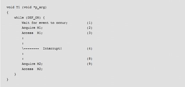
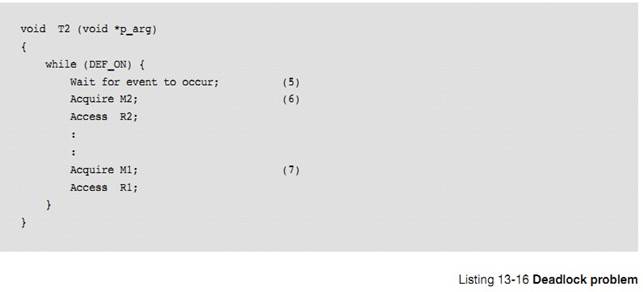
L13-16��1���ٶ����� T1 ���ȴ������鷢�������� 1 ��ִ�С�
L13-16(1) Assume that the event that task T1 is waiting
for occurs and T1 is now the highest priority task that must execute.
L13-16��2������ T1 ���� M1��(mutex 1)
L13-16(2) Task T1 executes and acquires M1.
L13-16��3������ T1 ������Դ R1��
L13-16(3) Resource R1 is accessed.
L13-16��4���жϷ������ж���ʹ�������� T2���������� T2 �����ȼ��������� T1��CPU �л������� T2��
L13-16(4) An interrupt occurs causing the CPU to switch
to task T2 as T2 is now the highest-priority task. Actually, this could be a
blocking call when the task is suspended and the CPU is given to another task.
L13-16��5�����жϼ������� T2 ���ȴ����¼���
L13-16(5) The ISR is the event that task T2 was waiting
for and therefore T2 resumes execution.
L13-16��6������ T2 ���� M2 ��ռ����Դ R2��
L13-16(6)
Task T2 acquires mutex M2 and is able to access resource R2.
L13-16��7������T2���� M1������ M1 �ѱ����� T1 ռ�á����� T2
������
L13-16(7)
Task T2 tries to acquire mutex M1, but ��C/OS-III knows that mutex M1 is owned
by another task.
L13-16��8��uC/OS-III ������� T1��
L13-16(8) ��C/OS-III switches back to task T1 because Task
T2 can no longer continue. It needs mutex M1 to access resource R1.
L13-16��9����ʱ���� T1 ���� M2������ M2 �Ѿ������� T2 ռ�á�
L13-16(9) Task T1 now tries to access mutex M2 but,
unfortunately, mutex M2 is owned by task T2. At this point, the two tasks are
deadlocked.
��ʱ������������ȴ�����������������������·�ʽ��ֹ������
Techniques
used to avoid deadlocks are for tasks to:
�� ͬһ��ʱ�䲻Ҫ�������һ�� mutex
Never
acquire more than one mutex at a time
�� ��Ҫֱ�ӵ����� mutex��������ŵ����������кͿ����뺯���У�
Never
acquire a mutex directly (i.e., let them be hidden inside drivers and reentrant
library calls)
�� �ڴ���֮ǰ�Ȼ��ȫ������Ҫ�� mutex
Acquire
all resources before proceeding
�� �������ͬ����˳��������Դ
Always
acquire resources in the same order
�������ź����� mutex ʱ�����������ޣ������ܷ�ֹ����������ͬ�������������Ժ��ٴγ��֡�
��C/OS-III
allows the calling task to specify a timeout when acquiring a semaphore or a
mutex. This feature allows a deadlock to be broken, but the same deadlock may
then recur later, or many times later. If the semaphore or mutex is not
available within a certain period of time, the task requesting the resource
resumes execution. ��C/OS-III returns an error code indicating that a timeout
occurred. A return error code prevents the task from thinking it has properly
obtained the resource.
����֮ǰ�Ȼ��ȫ������Ҫ�� mutex ��α�������б� 13-7
The
pseudo-code avoids deadlocks by first acquiring all resources as shown in
Listing 13-17.
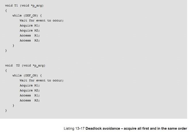
�������ͬ����˳��������Դ��α������ 13-18 ��ʾ�����������������ǰ�����ӣ��������Ȼ��ȫ���� mutex��������������������ͬ˳��������Դ��
The
pseudo-code to acquire all of the mutexes in the same order is shown in Listing
13-18. This is similar to the previous example, except that it is not necessary
to acquire all the mutexes first, only to make sure that the mutexes are
acquired in the same order for both tasks.
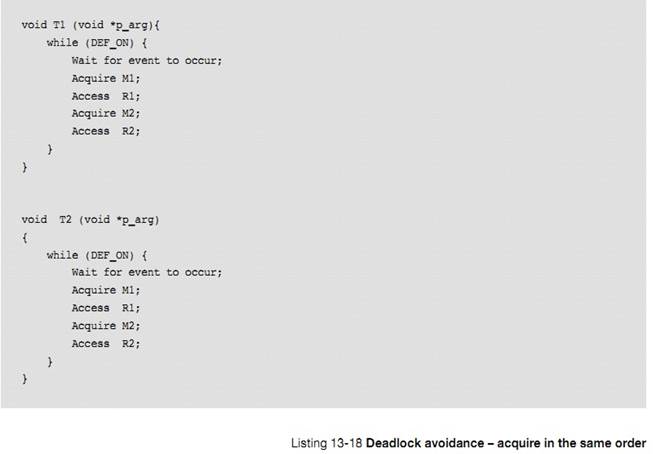
mutex
��ʹ�������ڷ��ʹ�����Դ�IJ����ܷ����ִ�С����13-4��
The
mutual exclusion mechanism used depends on how fast code will access the shared
resource, as shown in Table 13-4.
|
��Դ������ʽ
|
ʲôʱ�����
|
|
���жϷ�ʽ
Disable/Enable
Interrupts
|
�ܺܿ�ؽ������ʹ�����Դ�����Ƽ�ʹ�����ַ�������Ϊ�ᵼ���ж��ӳ�
When access to shared
resource is very quick (reading from or writing to just a few variables) and
the access is actually faster than ��C/OS-III��s
interrupt disable time.
It is highly
recommended to not use this method as it impacts interrupt latency.
|
|
����������ʽ
Locking/Unlocking the
Scheduler
|
���ʹ�����Դ�ȽϾ�ʱ��
When
access time to the shared resource is longer than ��C/OS-III��s interrupt disable time, but shorter than ��C/OS-III��s scheduler lock time. Locking
the scheduler has the same effect as making the task that locks the scheduler
the highest priority task.
It is recommended to
not use this method since it defeats the purpose of using ��C/OS-III.
However, it��s a better method than disabling
interrupts as it does not impact interrupt latency.
|
|
�ź�����ʽ
Semaphores
|
���ù�����Դ�����������ʹ��ʱ�����ź������ܻᵼ�����ȼ���ת��
When all tasks that
need to access a shared resource do not have deadlines. This is because
semaphores can cause unbounded priority inversions. However, semaphore
services are slightly faster (in execution time) than mutual exclusion
semaphores.
|
|
mutex ��ʽ
Mutual Exclusion
Semaphores
|
�Ƽ�ʹ�����ַ������ʹ�����Դ�����䵱����Ҫ���ʵĹ�����Դ�н�ֹʱ�䡣
This is the preferred
method for accessing shared resources, especially if the tasks that need to
access a shared resource have deadlines.
uC/OS-III �� mutex �����õ����ȼ��������ɷ�ֹ���ȼ����á�
Remember that mutual
exclusion semaphores have a built-in priority inheritance mechanism, which
avoids unbounded priority inversions.
Ȼ����mutex ��ʽ�����ź�����ʽ��mutex ��ִ�ж���IJ������ı��ź��������ȼ�
However, mutual
exclusion semaphore services are slightly slower (in execution time) than
semaphores, because the priority of the owner may need to be changed, which
requires CPU processing.
|
14��ͬ��
����½���Ҫ��������������� ISR ����������ͬ�����е�
This
chapter focuses on how tasks can synchronize their activities with Interrupt
Service Routines (ISRs), or other tasks.
�� ISR ִ��ʱ�������Է����ź�������Ϣ���������������ȴ����¼�������ISR ִ����Ϻ��õ��������Ƽ�������ִ���ж�����Ĵֲ�������Ϊ��������ٹ��жϵ�ʱ�������ڵ��ԡ�
When
an ISR executes, it can signal a task telling the task that an event of
interest has occurred. After signaling the task, the ISR exits and, depending
on the signaled task priority, the scheduler is run. The signaled task may then
service the interrupting device, or otherwise react to the event. Serving
interrupting devices from task level is preferred whenever possible, since it
reduces the amount of time that interrupts are disabled and the code is easier
to debug.
uC/OS-III
������ͬ�������ֻ��ƣ��ź������¼���־�顣
There
are two basic mechanisms for synchronizations in ��C/OS-III: semaphores and
event flags.
����� 13 �������ܣ��ź����Ǿ�������������ں����ṩ��Э����ơ��ź���������ڿ��ƹ�����Դ�ķ��ʡ��ź��������� ISR ������䡢������������ͬ������ͼ 14-1 ��ʾ��
As defined
in Chapter 13, ��Resource Management�� on page 209, a semaphore is a protocol
mechanism offered by most multitasking kernels. Semaphores were originally used
to control access to shared resources. However, better mechanisms exist to
protect access to shared resources, as described in Chapter 12. Semaphores are
best used to synchronize an ISR to a task, or synchronize a task with another
task as shown in Figure 14-1.
ͼ���ź���������һ�����ģ����ڱ������¼������ı�־���ź����ij�ʼֵͨ��Ϊ 0������û���¼�������
Note
that the semaphore is drawn as a flag to indicate that it is used to signal the
occurrence of an event. The initial value for the semaphore is typically zero
(0), indicating the event has not yet occurred.
��N����ʾ�ź������Ա��ۼơ���ʼ��ʱҲ��������Ϊ�� 0 ֵ�������Ѿ����¼�������ISR ����������ύ�ź�����Σ��ź�������ֵ���¼���ź���һ���ɱ����ٴΡ�
The
value ��N�� next to the flag indicates that the semaphore can accumulate events
or credits. It is possible to initialize the semaphore with a value other than
zero, indicating that the semaphore initially contains that number of events.
An ISR (or a task) can post (or signal) multiple times to a semaphore and the
semaphore will remember how many times it was posted.
�����Աߵ�ɳ©��ʾ����������õȴ����ź��������ޡ�
Also,
the small hourglass close to the receiving task indicates that the task has an
option to specify a timeout. This timeout indicates that the task is willing to
wait for the semaphore to be signaled (or posted to) within a certain amount of
time. If the semaphore is not signaled within that time, ��C/OS-III resumes the
task and returns an error code indicating that the task was made ready to run
because of a timeout and not the semaphore was signaled.
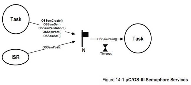
�ź�����������غ������ 14-1 ��ʾ��ע��������е��ź������������Ա�������ã����� ISR ��ֻ�ܵ��� OSSemPost()��
There
are a number of operations to perform on semaphores as summarized in Table 14-1
and Figure 14-1. However, in this chapter, we will only discuss the three
functions used most often: OSSemCreate(), OSSemPend(), and OSSemPost(). The
other functions are described in Appendix A, ����C/OS-III API Reference Manual��
on page 375. Also note that every semaphore function is callable from a task,
but only OSSemPost() can be called by an ISR
|
������
|
����
|
|
OSSemCreate()
|
����һ���ź���
Create a semaphore
|
|
OSSemDel()
|
ɾ��һ���ź���
Delete a semaphore
|
|
OSSemPend()
|
�ȴ�һ���ź���
Wait on a semaphore
|
|
OSSemPendAbort()
|
ȡ���ȴ����ź���
Abort the wait on a semaphore
|
|
OSSemPost()
|
�ύһ���ź���
Signal a semaphore
|
|
OSSemSet()
|
�����ź�������ֵ
Force the semaphore count to a desired value
|
�� 14-1 �ź����� API �ܽ�
����ͬ��ʱ���ź�������ֵ�м�¼�������ź����ɱ�����Ĵ������ü���ֵ�� 0 �� 25565535���� 0 �� 4294987295 ֮�䣬�����ڸü���������λ����8λ��16 λ��32 λ���ر�ģ��ź�������ֵ������ΪOS_SEM_CTR(�� OS_TYPE.H)��
When
used for synchronization, a semaphore keeps track of how many times it was
signaled using a counter. The counter can take values between 0 and 255,
65,535, or 4,294,967,295, depending on whether the semaphore mechanism is
implemented using 8, 16, or 32 bits, respectively. For ��C/OS-III, the maximum value
of a semaphore is determined by the data type OS_SEM_CTR (see OS_TYPE.H), which
is changeable, as needed (assuming access to ��C/OS-III��s source code). Along
with the semaphore��s value, ��C/OS-III keeps track of tasks waiting for the
semaphore to be signaled.
14-1-1 ����ͬ��
ͼ 14-2 ��ʾ��ͨ���ź�������������� ISR ������ͬ����ͨ���ź����Ĵ��ݣ�������� ISR ���������ˡ�ʹ���ź���ʵ��ͬ����������ͬ����
Figure
14-2 shows that a task can be synchronized with an ISR (or another task) by
using a semaphore. In this case, no data is exchanged, however there is an indication
that the ISR or the task (on the left) has occurred. Using a semaphore for this
type of synchronization is called a unilateral rendezvous.
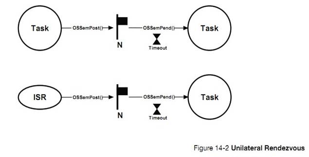
������Ҫʹ�� I/O �˿ڣ����������ź��������� OSSemPend()��
A
unilateral rendezvous is used when a task initiates an I/O operation and waits
(i.e., call OSSemPend()) for the semaphore to be signaled (posted).
��������ɶ� I/O �˿ڵķ�����ɺͱ������ OSSemPost()�ͷ�����ź�������������ǵ���ͬ���ġ���ͼ 14-3������������ ISR ������������б� 14-1 ��ʾ��
When
the I/O operation is complete, an ISR (or another task) signals the semaphore
(i.e., calls OSSemPost()), and the task is resumed. This process is also shown
on the timeline of Figure 14-3 and described below. The code for the ISR and
task is shown in Listing 14-1.
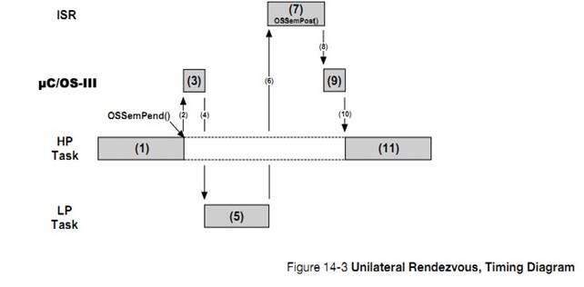
F14-3��1������ H ��ִ�С��������� ISR ͬ����Ҳ���ǵȴ� ISR �ķ�������Ȼ����� OSSemPend()����һ���ź�����
F14-3(1) A high priority task is executing. The
task needs to synchronize with an ISR (i.e., wait for the ISR to occur) and
call OSSemPend().
F14-3��2��ת�� uC/OS-III ������
F14-3��3��OSSemPend()����ز�����
F14-3��4����Ϊ ISR ��δ���������� H �����������У������õ�������
F14-3(4) Since the ISR has not occurred, the task
will be placed in the waiting list for the semaphore until the event occurs The
scheduler in ��C/OS-III will then select the next most important task and
context switch to that task.
F14-3��5������ L ��ִ�С�
F14-3(5) The low-priority task executes.
F14-3��6���жϷ��������� L �����棬CPU ת�� ISR��
F14-3��7����ʼִ�� ISR��
F14-3(7) The event that the original task was
waiting for occurs. The lower-priority task is immediately preempted (assuming
interrupts are enabled), and the CPU vectors to the interrupt handler for the
event.
F14-3��8��ISR ���
OSSemPost()�ύ������ H ���ȴ����ź�����
F14-3��9���ź������������� H��
F14-3(9) The ISR handles the interrupting device
and then calls OSSemPost() to signal the semaphore. When the ISR completes,
��C/OS-III is called.
F14-4��10������ H ���������������� CPU
�Ŀ���Ȩ�������� H��
F14-3(10) ��C/OS-III notices that a higher-priority task
is waiting for this event to occur and context switches back to the original
task.
F14-4��11������ H ����ź�����������ִ�С�
F14-3(11) The original task resumes execution immediately
after the call to OSSemPend().
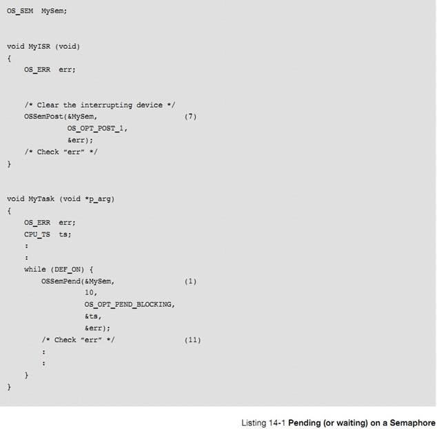
ע�һЩ��Ȥ�����飺��һ��uC/OS-III ���������ȼ���ߵľ�������ִ�У���������� CPU���ڶ�������ȴ��ź���ʱ�Dz����� CPU ��ִ��ʱ�䡣����������ȴ����ź�������ʱ�� uC/OS-III ��Ѹ�ٵظ�֪�������õ�������
A
few interesting things are worth noting about this process. First, the task
does not need to know about the details of what happens behind the scenes. As
far as the task is concerned, it called a function (OSSemPend()) that will
return when the event it is waiting for occurs. Second, ��C/OS-III maximizes the
use of the CPU by selecting the next most important task, which executes until
the ISR occurs. In fact, the ISR may not occur for many milliseconds and,
during that time, the CPU will work on other tasks. As far as the task that is
waiting for the semaphore is concerned, it does not consume CPU time while it
is waiting. Finally, the task waiting for the semaphore will execute
immediately after the event occurs (assuming it is the most important task that
needs to run).
14-1-2 �ź�������ֵ
ǰ���ᵽ���ź�������ֵ�б����������ܱ�������ٴΡ����仰˵���� ISR �ύ���ź��� n �Σ���ô���ź�������ֵ�ͻ����� n����ͼ 14-4
As previously
mentioned, a semaphore ��remembers�� how many times it was signaled (or posted
to). In other words, if the ISR occurs multiple times before the task waiting
for the event becomes the highest-priority task, the semaphore will keep count
of the number of times it was signaled. When the task becomes the highest
priority ready-to-run task, it will execute without blocking as many times as
there were ISRs signaled. This is called Credit Tracking and is illustrated in
Figure 14-4 and described below.
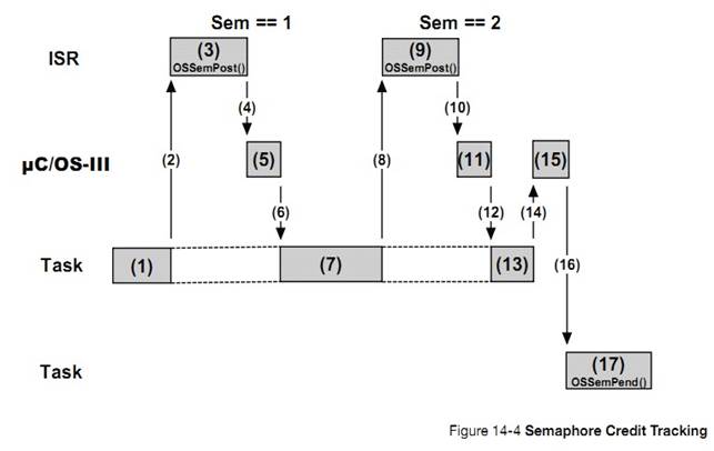
F14-4��1�������ȼ����� H ��ִ�С�
F14-4(1)
A high-priority task is executing.
F14-4��2���жϷ�����
F14-4��3��ISR ���ύ��һ���ź�����
F14-4(3) An event meant for a lower-priority task
occurs which preempts the task (assuming interrupts are enabled). The ISR
executes and posts the semaphore.
At
this point the semaphore count is 1.
F14-4��4���ź������ύ��uC/OS-III �����һЩ������
F14-4��5��uC/OS-III ִ����Ӧ������
F14-4��6������û�и������ȼ���������uC/OS-III ����ִ������ H��
F14-4(6) ��C/OS-III is called at the end of the ISR
to see if the ISR caused a higher-priority task to be ready to run. Since the
ISR was an event that a lower-priority task was waiting on, ��C/OS-III will
resume execution of the higher-priority task at the exact point where it was
interrupted.
F14-4��7������ H ��ִ�С�
F14-4(7)
The high-priority task is resumed and continues execution.
F14-4��8���жϷ�����
F14-4��9���ڶ����жϷ����ˣ�ISR ���ύ��һ���ź����� F14-4��10���ź������ύ��uC/OS-III
�����һЩ������
F14-4(9) The interrupt occurs a second time. The
ISR executes and posts the semaphore.
At
this point the semaphore count is 2.
F14-4��11��uC/OS-III ִ����Ӧ������
F14-4��12������û�и������ȼ���������uC/OS-III ����ִ������ H��
F14-4(12) ��C/OS-III is called at the end of the ISR to
see if the ISR caused a higher-priority task to be ready to run. Since the ISR
was an event that a lower-priority task was waiting on, ��C/OS-III resumes
execution of the higher-priority task at the exact point where it was
interrupted.
F14-4��13������ H ��ִ�С�
F14-4��14������ H ִ����ϡ�
F14-4(14) The high-priority task resumes execution and
actually terminates the work it was doing. This task will then call one of the
��C/OS-III services to wait for ��its�� event to occur.
F14-4��15��uC/OS-III ִ����Ӧ���������л�������
F14-4��16��uC/OS-III �� CPU �Ŀ���Ȩ�������� L��
F14-4(16) ��C/OS-III will then select the next most
important task, which happens to be the task waiting for the event and will
context switch to that task.
F14-4��17������ L ��ִ�С�
F14-4(17) The new task executes and will know that the
ISR occurred twice since the semaphore count is two. The task will handle this
accordingly.
14-1-3 �������ȴ�һ���ź���
����������ͬʱ�ȴ�ͬ�����ź���������ÿ�����������˶�ʱ���ޡ���ͼ 14-5 ��ʾ
It
is possible for more than one task to wait on the same semaphore, each with its
own timeout as illustrated in Figure 14-5.
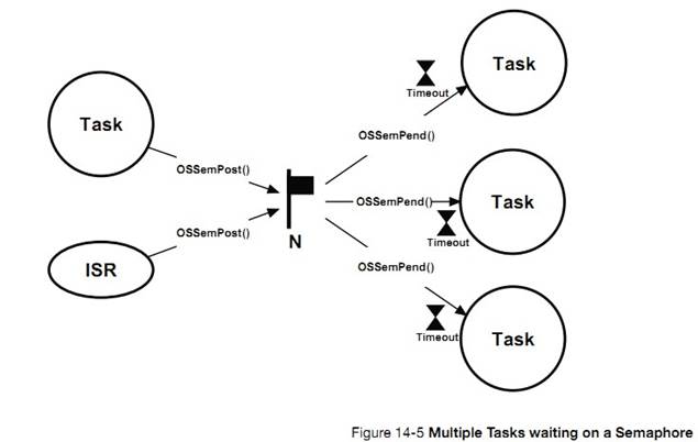
�����ź������ύʱ��uC/OS-III ���ù�����������ȼ���ߵ����������Ȼ����Ҳ�����ù�����������е���������������㲥�ź���������OSSemPost()ʱѡ����� OS_OPT_POST_ALL ����ʵ�ֹ㲥�Ĺ��ܡ�
When
the semaphore is signaled (whether by an ISR or task), ��C/OS-III makes the
highest-priority task waiting on the semaphore ready to run. However, it is
also possible to specify that all tasks waiting on the semaphore be made ready
to run. This is called broadcasting and is accomplished by specifying
OS_OPT_POST_ALL as an option when calling OSSemPost(). If any of the waiting
tasks has a higher priority than the previously running task, ��C/OS-III will
execute the highest-priority task made ready by OSSemPost().
�㲥���ڶ��������ͬ����Ȼ������������Ҫ�벻���ź�����������е���������ͬ��������ͬʱʹ���ź������¼���־��ʵ��ͬ���Ĺ��ܡ�
Broadcasting
is a common technique used to synchronize multiple tasks and have them start
executing at the same time. However, some of the tasks that we want to
synchronize might not be waiting for the semaphore. It is fairly easy to
resolve this problem by combining semaphores and event flags. This will be
described after examining event flags.
����ͨ�������ź���ʵ��ͬ����ÿ���������ڽ����ź�����ͨ�������ڽ����ź����������Լ��ź���ͨ�ŵĴ�����Ҹ�����Ч����ͼ 14-7 ��ʾ
Signaling
a task using a semaphore is a very popular method of synchronization and, in
��C/OS-III, each task has its own built-in semaphore. This feature not only
simplifies code, but is also more efficient than using a separate semaphore
object. The semaphore, which is built into each task, is shown in Figure 14-7.
Task
semaphore services in ��C/OS-III start with the OSTaskSem???() prefix, and the
services available to the application programmer are described in Appendix A,
����C/OS-III API Reference Manual�� on page 375. Task semaphores are built into
��C/OS-III and cannot be disabled at compile time as can other services. The
code for task semaphores is found in OS_TASK.C.
Use
this feature if the code knows which task to signal when the event occurs. For
example, if receiving an interrupt from an Ethernet controller, signal the task
responsible for processing the received packet as it is preferable to perform
this processing using a task instead of the ISR.
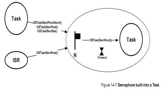
�������ڽ����ź�����صĺ��������� OSTaskSem???()Ϊǰ�ġ���صĴ��붼�� OS_TASK.C �С���� 14-2
There
are a number of operations to perform on task semaphores, summarized in Table
14-2.
|
������
|
����
|
|
OSTaskSemPend()
|
�ȴ�һ�������ź���
Wait on a task semaphore
|
|
OSTaskSemPendAbort()
|
ȡ���ȴ�
Abort the wait on a task semaphore
|
|
OSTaskSemPost()
|
�����ź���������
Signal a task
|
|
OSTaskSemSet()
|
�����ź�������ֵ
Force the semaphore count to a desired value
|
�� 14-2 �����ڽ��ź��������ܽ�
14-2-2���𣨵ȴ��������ź���
��������ʱ��Ҳ���ڽ�һ���ź������ź�������ֵ��ʼ��Ϊ0.�ȴ������ź������б� 14-6 ��ʾ��
When
a task is created, it automatically creates an internal semaphore with an
initial value of zero (0). Waiting on a task semaphore is quite simple, as
shown in Listing 14-6.
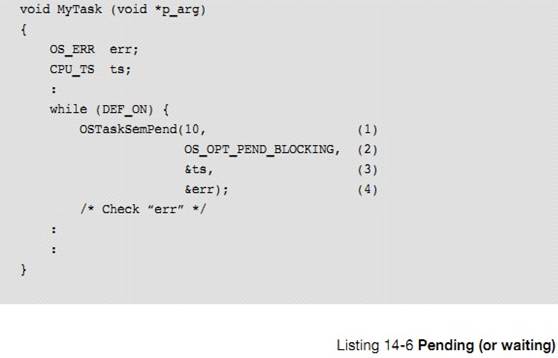
L14-6��1������ͨ������ OSTaskSemPend()�ȴ������ź���������������һ������Ϊ�ȴ����ޣ���ʱ��Ϊ��λ��
L14-6(1)
A task pends (or waits) on the task semaphore by calling OSTaskSemPend(). There
is no need to specify which task, as the current task is assumed. The first
argument is a timeout specified in number of clock ticks. The actual timeout
obviously depends on the tick rate. If the tick rate (see OS_CFG_APP.H) is set
to 1000, a timeout of 10 ticks represents 10 milliseconds. Specifying a timeout
of zero (0) means that the task will wait forever for the task semaphore.
L14-6
�� 2 ���ڶ��������ǹ���ʽ��һ�������ַ�ʽ��
OS_OPT_PEND_BLOCKING
��
OS_OPT_PEND_NON_BLOCKING��
L14-6(2) The second argument specifies how to
pend. There are two options: OS_OPT_PEND_BLOCKING and OS_OPT_PEND_NON_BLOCKING.
The blocking option means that, if the task semaphore has not been signaled (or
posted to), the task will wait until the semaphore is signaled, the pend is
aborted by another task or, until the timeout expires.
L14-6��3����������ʱ���ò����б������ź������ύʱ��ʱ�����
L14-6(3) When the semaphore is signaled, ��C/OS-III
reads a ��timestamp�� and places it in the receiving task��s OS_TCB. When
OSTaskSemPend() returns, the value of the timestamp is placed in the local
variable ��ts��. This feature captures ��when�� the signal actually happened. Call
OS_TS_GET() to read the current timestamp and compute the difference. This
establishes how long it took for the task to receive the signal from the
posting task or ISR.
L14-6��4����������ʱ������ִ�н��������һ��������š�
�ύ����ǣ������ź���ISR ������ͨ������ OSTaskSemPost()�ύ�����ź��������б�14-7 ��ʾ
L14-6(4) OSTaskSemPend() returns an error code
based on the outcome of the call. If the call was successful, err will contain
OS_ERR_NONE. If not, the error code will indicate the reason of the error (see
Appendix A, ����C/OS-III API Reference Manual�� on page 375 for a list of possible
error code for OSTaskSemPend().
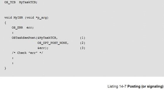
L14-7��1��ͨ������ OSTaskSemPost()�������ź����ύ�����ò���ΪĿ������� OS_TCB ��ַ��
L14-7(1) A task posts (or signals) the task by
calling OSTaskSemPost(). It is necessary to pass the address of the desired
task��s OS_TCB. Of course, the task must exist.
L14-7��2���������Ϊ�ύ��ʽ��ѡ��һ���������ύ��ʽ��
OS_OPT_POST_NONE
�ύ��ɺ���õ�������
OS_OPT_POST_NO_SCHED
�ύ��ɺ���õ����������ύ����ź���ʱ������ִֻ��һ�ε��ȣ�
L14-7(2) The next argument specifies how the user
wants to post. There are only two choices.
Specify
OS_OPT_POST_NONE, which indicates the use of the default option of calling the
scheduler after posting the semaphore.
Or,
specify OS_OPT_POST_NO_SCHED to indicate that the scheduler is not to be called
at the end of OSTaskSemPost(), possibly because there will be additional
postings, and rescheduling would take place when finished (the last post would
not specify this option).
L14-7��3����������ʱ������ִ�н��������һ��������š�
˫��ͬ��
L14-7(3) OSTaskSemPost() returns an error code based
on the outcome of the call. If the call was successful, err will contain
OS_ERR_NONE. If not, the error code will indicate the reason of the error (see
Appendix A, ����C/OS-III API Reference Manual�� on page 375 for a list of possible
error codes for OSTaskSemPost().
�������������������ź���ʵ��˫��ͬ������ͼ 14-8�������� ISR �䲻��˫��ͬ������Ϊ ISR �в��ܵȴ��ź�����ISR �в������������У���
Two
tasks can synchronize their activities by using two task semaphores, as shown
in Figure 14-8, and is called a bilateral rendezvous. A bilateral rendezvous is
similar to a unilateral rendezvous, except that both tasks must synchronize
with one another before proceeding. A bilateral rendezvous cannot be performed
between a task and an ISR because an ISR cannot wait on a semaphore.
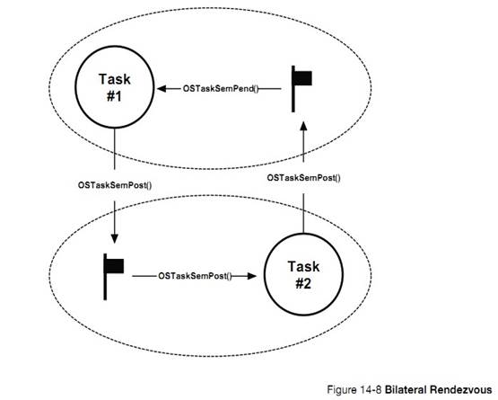
˫��ͬ���Ĵ������б� 14-8 ��ʾ����Ȼ��˫��ͬ�������������ⲿ�ź���ʵ�֣���ʹ�������ź�������Ӽ�
The
code for a bilateral rendezvous is shown in Listing 14-8. Of course, a
bilateral rendezvous can use two separate semaphores, but the built-in task
semaphore makes setting up this type of synchronization quite straightforward.
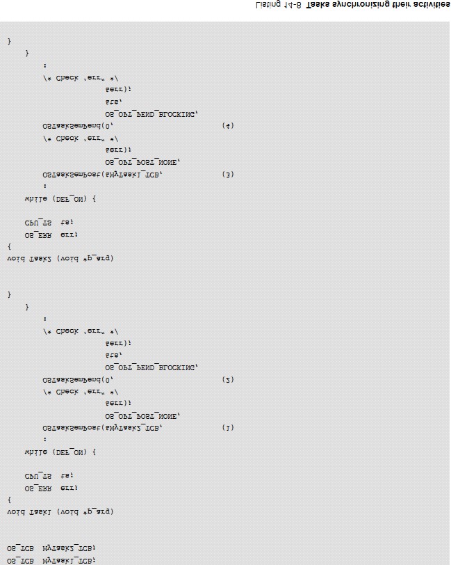
L14-8��1������ 1 �����ź��������� 2��
L14-8(1) Task #1 is executing and signals Task
#2��s semaphore.
L14-8��2������ 1 �ȴ����ڲ����ź�����������
2 ͬ������Ϊ���� 2 ��δ��ִ�У����� 1 �����𣬵ȴ����� 2 ���䷢���ź�����
L14-8(2) Task #1 pends on its internal semaphore
to synchronize with Task #2. Because Task #2 has not executed yet, Task #1 is
blocked waiting on its semaphore to be signaled. ��C/OS-III context switches to
Task #2.
L14-8��3���л������� 2 ��ִ�У������� 1 �����ź�����
L14-8(3) Task #2 executes, and signals Task #1��s
semaphore.
L14-8��4����ʱ���� 2 ������ 1 ͬ����������� 1 ���ȼ��ϸߣ�uC/OS-III �л������� 1���������� 2 ����ִ�С�
L14-8(4) Since it has already been signaled, Task
#2 is now synchronized to Task #1. If Task #1 is higher in priority than Task
#2, ��C/OS-III will switch back to Task #1. If not, Task #2 continues execution.
������Ҫ�����¼�ͬ��ʱ����ʹ���¼���־�������е�����һ���¼�����ʱ����������������(OR)�������е��¼�������ʱ���������������루AND������ͼ 14-9 ��ʾ��
Event
flags are used when a task needs to synchronize with the occurrence of multiple
events. The task can be synchronized when any of the events have occurred,
which is called disjunctive synchronization (logical OR). A task can also be
synchronized when all events have occurred, which is called conjunctive
synchronization (logical AND). Disjunctive and conjunctive synchronization are
shown in Figure 14-9.
�û����Դ���������¼���־�飨������ RAM����uC/OS-III �����¼���־����صĺ��������� OSFlag???()Ϊǰ�����¼���־����صĺ������붼�� OS_FLAG.C �С�
The
application programmer can create an unlimited number of event flag groups
(limited only by available RAM). Event flag services in ��C/OS-III start with
the OSFlag???() prefix. The services available to the application programmer
are described in Appendix A, ����C/OS-III API Reference Manual�� on page 375.
���� OS_CFG.H �е�
OS_CFG_FLAG_EN Ϊ 1 �����¼���־�鹦�ܡ�
The
code for event flag services is found in the file OS_FLAG.C, and is enabled at
compile time by setting the configuration constant OS_CFG_FLAG_EN to 1 in
OS_CFG.H.
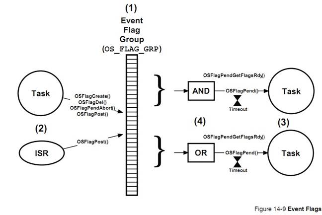
F14-9��1���¼���־���� uC/OS-III ���ں˶����� OS_FLAG_GRP Ϊ�������ͣ��� OS.H���� �������� 8 λ��16 λ��32 λ��������OS_TYPE.H ��������� OS_FLAGS���¼���־���е�λ���������ȴ��¼��Ƿ����ı�־���¼���־������ڴ�����ʹ�á�
F14-9(1) A ��C/OS-III ��event flag group�� is a kernel
object of type OS_FLAG_GRP (see OS.H), and consists of a series of bits (8-,
16- or 32-bits, based on the data type OS_FLAGS defined in OS_TYPE.H). The
event flag group also contains a list of tasks waiting for some (or all) of the
bits to be set (1) or clear (0). An event flag group must be created before it
can be used by tasks and ISRs. Create event flags prior to starting ��C/OS-III,
or by a startup task in the application code.
F14-9��2������� ISR �����ύ��־��Ȼ����ֻ��������Խ����¼���־���еȴ�����������ɾ����ȡ���ȴ���ֻ������������������¼���־���еȴ���
F14-9(2) Tasks or ISRs can post to event flags. In
addition, only tasks can create, delete, and stop other task from pending on
event flag groups.
F14-9��3��������Եȴ��¼���־���е������λ�����á��ȴ�Ҳ���Ա��������ޣ���ʱ��Ϊ��λ��
F14-9(3) A task can wait (i.e., pend) on any
number of bits in an event flag group (i.e., a subset of all the bits). As with
all ��C/OS-III pend calls, the calling task can specify a timeout value such
that if the desired bits are not posted within a specified amount of time (in
ticks), the pending task is resumed and informed about the timeout.
F14-9��4������ȴ��¼���־���е�λ�����Ա�����Ϊ OR ģʽ�������� AND ģʽ��
F14-9(4) The task can specify whether it wants to
wait for ��any�� subset of bits (OR) to be set (or clear), or wait for ��all�� bits
in a subset of bit (AND) to be set (or clear).
There
are a number of operations to perform on event flags, as summarized in Table
14-3.
|
������
|
����
|
|
OSFlagCreate()
|
����һ���¼���־��
Create an event flag group
|
|
OSFlagDel()
|
ɾ��һ���¼���־��
Delete an event flag group
|
|
OSFlagPend()
|
���¼���־���й���
Pend (i.e., wait) on an event flag group
|
|
OSFlagPendAbort()
|
ȡ���ȴ�
Abort waiting on an event flag group
|
|
OSFlagPendGetFalgsRdy()
|
����¼���־���е�����������λ
Get flags that caused task to become ready
|
|
OSFlagPost()
|
�ύ��־���¼���־��
Post flag(s) to an event flag group
|
�� 14-3 �¼���־�� API �ܽ�
14-3-1 ʹ���¼���־��
������� ISR �ύ��־���¼���־�飬��������������ᱻ������
When
a task or an ISR posts to an event flag group, all tasks that have their wait
conditions satisfied will be resumed.
�¼���־����λ�ĺ������û����壬Ӧ���п����ж���¼���־�顣���¼���־���У����Զ���λ 0 ��ʾ�¶ȹ��ͣ����¶ȴ��������գ���λ 1 ��ʾ��ѹ���ͣ�λ 2 ��ʾij�����ر����µȡ������ ISR �����Щ������������OSFlagPost()������Ӧ�ı�־λ��������Ե��� OSFlagPend()�����Ӧ�ı�־�Ƿ�����
It��s
up to the application to determine what each bit in an event flag group means
and it is possible to use as many event flag groups as needed. In an event flag
group you can, for example, define that bit #0 indicates that a temperature
sensor is too low, bit #1 may indicate a low battery voltage, bit #2 could
indicate that a switch was pressed, etc. The code (tasks or ISRs) that detects
these conditions would set the appropriate event flag by calling OSFlagPost()
and the task(s) that would respond to those conditions would call OSFlagPend().
�б� 14-9 ��ʾ�����ʹ���¼���־�顣
Listing
14-9 shows how to use event flags.

L14-9��1��������Ӧλ����ʾ�ĺ��塣
L14-9(1) Define some bits in the event flag group.
L14-9��2������һ���¼���־�飬������Ϊ OS_FLAG_GRP��Ϊ��˵�����ٶ��¼���־���λ��Ϊ 16������ OS_TYPE.H �����ã�
L14-9(2) Declare an object of type OS_FLAG_GRP.
This object will be referenced in all subsequent ��C/OS-III calls that apply to
this event flag group. For the sake of discussions, assume that event flags are
declared to be 16-bits in OS_TYPE.H (i.e., of type CPU_INT16U).
L14-9��3���¼���־����뱻���������ʹ�ã������Ӧ�õ��������루����˵��ʼ�����룩�оʹ����¼���־�顣����������У��¼���־�鱻����һ�����֣���ȫ��λ�����㡣
L14-9(3) Event flag groups must be ��created��
before they can be used. The best place to do this is in your startup code as
it ensures that no tasks, or ISR, will be able to use the event flag group
until ��C/OS-III is started. In other words, the best place is to create the
event flag group is in main(). In the example, the event flag was given a name
and all bits start in their cleared state (i.e., all zeros).
L14-9��4���ٶ� MyTask()���¼���־���б�����
L14-9(4) Assume that the application created
��MyTask()�� which will be pending on the event flag group.
L14-9��5������ OSFlagPend()���������¼���־���ַ������ͻᱻ�������¼���־���С�
L14-9(5) To pend on an event flag group, call
OSFlagPend() and pass it the address of the desired event flag group.
�ڶ�������������ȴ���Щλ����λ������������ 2 ��λ��
The
second argument specifies which bits the task will be waiting to be set
(assuming the task is triggered by set bits instead of cleared bits).
�����������ǵȴ�ʱ�ޡ�
Specify
how long to wait for these bits to be set. A timeout value of zero (0)
indicates that the task will wait forever. A non-zero value indicates the
number of ticks the task will wait until it is resumed if the desired bits are
not set.
���ĸ������ǵȴ��ķ�ʽ��������Ϊ OS_OPT_FLAG_SET_ANY����������λ��ֻҪ��һ��λ����λ������ͻᱻ����������������д���˵��¼���־���ύʱ��ʱ�����
Specifying
OS_OPT_FLAG_SET_ANY indicates that the task will wake up if either of the two
bits specified is set. A timestamp is read and saved when the event flag group
is posted to. This timestamp can be used to determine the response time to the
event.
�����������Ǹ��ݺ���ִ�н�����صĴ�����š�
OSFlagPend()
performs a number of checks on the arguments passed (i.e., did you pass NULL
pointers, invalid options, etc.), and returns an error code based on the
outcome of the call. If the call was successful ��err�� will be set to
OS_ERR_NONE.
L14-9��6���жϱ�����Ϊ����ص�ѹ������ѹ����ʱ���жϷ�����ISR ����Ҫ��������������ִ����Ӧ������
L14-9(6) An ISR (it can also be a task) is setup
to detect when the battery voltage of the product goes low (assuming the
product is battery operated). The ISR signals the task, letting the task
perform whatever corrective action is needed.
L14-9��7��ͨ������ OSFlagPost()������ISR �������¼���־������Ӧ��λ��������������ѡ�������λ����һ�����㡣
L14-9(7) The desired event flag group is specified
in the post call as well as which flag the ISR is setting. The third option
specifies that the error condition will be ��flagged�� as a set bit. Again, the
function sets ��err�� based on the outcome of the call.
�¼���־��ͨ�����ڱ�ʾ�Ķ��ݵ��¼���״̬��Ϣ��ͨ���ò�ͬ���¼���־�鴦�����б� 14-10��
Event
flags are generally used for two purposes: status and transient events.
Typically use different event flag groups to handle each of these as shown in
Listing 14-10.
ISR
��������Բ���һЩ״̬��Ϣ�������¶ȡ�ת�١���ѹ�ȡ�����״̬��Ϣʱһ�㲻���õȴ�ʱ�ޡ�
Tasks
or ISRs can report status information such as a temperature that has exceeded a
certain value, that RPM is zero on an engine or motor, or there is fuel in the
tank, and more. This status information cannot be ��consumed�� by the tasks
waiting for these events, because the status is managed by other tasks or ISRs.
Event flags associated with status information are monitored by other task by
using non-blocking wait calls.
ISR
��������Բ���һЩ���ݵ��¼����簴�¿��ء���ը�ȡ����ڶ����¼�ʱһ�������˵ȴ�ʱ�ޡ�
Tasks
will report transient events such as a switch was pressed, an object was
detected by a motion sensor, an explosion occurred, etc. The task that responds
to these events will typically block waiting for any of those events to occur
and ��consume�� the event.
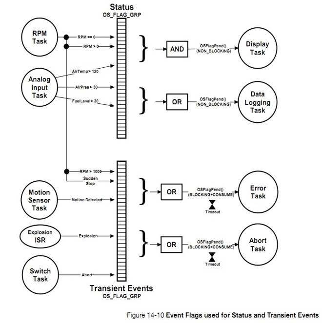
14-3-2 �¼���־���ڲ��ṹ
�û����Դ���������¼���־�飨�������ڴ������� RAM����ͨ������OS_CFG.H �е� OS_CFG_FLAG_EN Ϊ 1 �����¼���־�鹦�ܡ�
The
application programmer can create an unlimited number of event flag groups
(limited only by available RAM). Event flag services in ��C/OS-III start with
OSFlag and the services available to the application programmer are described
in Appendix A, ����C/OS-III API Reference Manual�� on page 375. Event flag
services are enabled at compile time by setting the configuration constant OS_CFG_FLAG_EN
to 1 in OS_CFG.H.
�¼���־����һ���ں˶������������� OS_FLAG_GRP ���壬������������ os_flag_grp ���壨�� OS.H�������¼���־����صĴ����� OS_FLAG.C �С����б� 14-10��
An
event flag group is a kernel object as defined by the OS_FLAG_GRP data type,
which is derived from the structure os_flag_grp (see OS.H) as shown in Listing
14-10.
The
services provided by ��C/OS-III to manage event flags are implemented in the
file OS_FLAG.C. ��C/OS-III licensees have access to the source code.
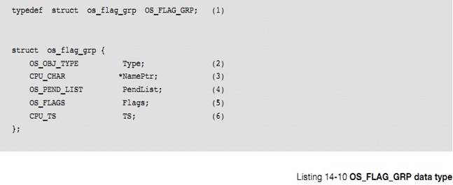
L14-10��1���� uC/OS-III �У����еĽṹ�嶼�ᶨ��һ���������͡�������"OS_"��ͷ����ȫ����д��
L14-10(1) In ��C/OS-III, all structures are given a data
type. In fact, all data types start with ��OS_�� and are uppercase. When an event
flag group is declared, simply use OS_FLAG_GRP as the data type of the variable
used to declare the event flag group.
L14-10��2���ṹ��ĵ�һ������Ϊ"Type"�����ڱ��ϸö���Ϊ�¼���־�顣
L14-10(2) The structure starts with a ��Type�� field, which
allows it to be recognized by ��C/OS-III as an event flag group. In other words,
other kernel objects will also have a ��Type�� as the first member of the
structure. If a function is passed a kernel object, ��C/OS-III will be able to
confirm that it is being passed the proper data type. For example, if passing a
message queue (OS_Q) to an event flag service (for example OSFlagPend()),
��C/OS-III will be able to recognize that an invalid object was passed, and
return an error code accordingly.
L14-10��3��ÿ���ں˶����Ա�����һ�����֡�
L14-10(3) Each kernel object can be given a name to make
them easier to be recognized by debuggers or ��C/Probe. This member is simply a
pointer to an ASCII string, which is assumed to be NUL terminated.
L14-10��4����Ϊ�����ж������ͬʱ�ȴ��¼���־���е��¼��������¼���־���а�����һ�����ڿ��ƹ�����еĽṹ�壨����ʮ�£���
L14-10(4) Because it is possible for multiple tasks to be
waiting (or pending) on an event flag group, the event flag group object
contains a pend list as described in Chapter 10, ��Pend Lists (or Wait Lists)��
on page 177.
L14-10��5���¼���־���а����˺ܶ��־λ����������б����˵�ǰ��Щ��־λ��״̬�������������Ϊ
8 λ��16 λ�� 32 λ�������� OS_TYPE.H �е� OS_FLAGS ��λ����
L14-10(5) An event flag group contains a series of flags
(i.e., bits), and this member contains the current state of these flags. The
flags can be implemented using either an 8-, 16- or 32-bit value depending on
how the data type OS_FLAGS is declared in OS_TYPE.H.
L14-10��6���¼���־���а�����һ���������洢�����һ�α�־���ύ��ʱ������û����벻��ֱ�ӷ����¼���־�飬����ͨ�� uC/OS-III �ṩ�ĺ��������¼���־�顣
L14-10(6) An event flag group contains a timestamp used
to indicate the last time the event flag group was posted to. ��C/OS-III assumes
the presence of a free-running counter that allows users to make time
measurements. When the event flag group is posted to, the free-running counter
is read and the value is placed in this field, which is returned when
OSFlagPend() is called. This value allows an application to determine either
when the post was performed, or how long it took for your the to obtain control
of the CPU from the post. In the latter case, call OS_TS_GET() to determine the
current timestamp and compute the difference.
Even
if the user understands the internals of the OS_FLAG_GRP data type, application
code should never access any of the fields in this data structure directly.
Instead, always use the APIs provided with ��C/OS-III.
�����¼���־�飬���б� 14-11 ��ʾ
Event
flag groups must be created before they can be used by an application as shown
in Listing 14-11.
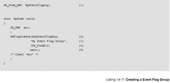
L14-11��1�������¼���־�顣
L14-11(1) The application must declare a variable of type
OS_FLAG_GRP. This variable will be referenced by other event flag services.
L14-11��2������ OSFlagGreate()����һ���¼���־�顣��һ������Ϊ�¼���־��ĵ�ַ��
L14-11(2) Create an event flag group by calling
OSFlagCreate() and pass the address to the event flag group allocated in (1).
L14-11��3�����¼���־�鸳�����֡����ֱ����Կ��ַ���β�����ǿո�
L14-11(3) Assign an ASCII name to the event flag group,
which can be used by debuggers or ��C/Probe to easily identify this event flag
group. ��C/OS-III stores a pointer to the name so there is no practical limit to
its size, except that the ASCII string needs to be NUL terminated.
L14-11��4��һ������£����¼���־���е����б�־λ��ʼ��Ϊ 0.
L14-11(4) Initialize the flags inside the event flag
group to zero (0) unless the task and ISRs signal events with bits cleared
instead of bits set. If using cleared bits, initialize all the bits to ones
(1).
L14-11��5������һ��������š����� OSFlagPend()������ȴ�һ��������־λ�����á�
L14-11(5) OSFlagCreate() returns an error code based on
the outcome of the call. If all the arguments are valid, err will contain
OS_ERR_NONE.
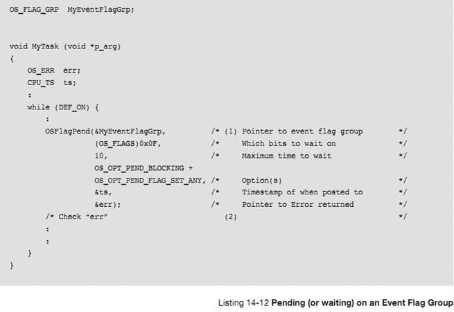
L14-12��1��OSFlagPend()��ʼʱ�ȼ���������Ч�ԡ����������ȴ��ı�־λ�����ã�OSFlagPend()�᷵���ĸ�λ�������ˡ�
L14-12(1)
When called, OSFlagPend() starts by checking the arguments passed to this
function to ensure they have valid values. If the bits the task is waiting for
are set (or cleared depending on the option), OSFlagPend() returns and indicate
which flags satisfied the condition. This is the outcome that the caller
expects.
�������Ϊ OS_OPT_PEND_NON_BLOCKING���������ȴ���λ��û�б����ã�OSFlagPend()���������أ������ش�����š�
If
the event flag group does not contain the flags that the caller is looking for,
the calling task might need to wait for the desired flags to be set (or
cleared). If specifying OS_OPT_PEND_NON_BLOCKING as the option (the task is not
to block), OSFlagPend() returns immediately to the caller and the returned
error code indicates that the bits have not been set (or cleared).
�������Ϊ OS_OPT_PEND_BLOCKING�����ȴ�λû�б�����ʱ����ᱻ���������С��������õȴ�ʱ�ޡ������е������������ȼ���ʽ����ģ����Ǻ����ȳ���ʽ����Ҳ���Ǻ�����ᱻ������ס�������Ϊ�������ĸ�λ�����ã�uC/OS-III ������������еġ�
If
specifying OS_OPT_PEND_BLOCKING as the option, the calling task will be
inserted in the list of tasks waiting for the desired event flag bits. The task
is not inserted in priority order but simply inserted at the beginning of the
list. This is done because whenever bits are set (or cleared), it is necessary
to examine all tasks in this list to see if their desired bits have been
satisfied.
If
further specifying a non-zero timeout, the task will also be inserted in the
tick list. A zero value for a timeout indicates that the calling task is
willing to wait forever for the desired bits.
The
scheduler is then called since the current task is no longer able to run (it is
waiting for the desired bits). The scheduler will run the next highest-priority
task that is ready to run.
When
the event flag group is posted to and the task that called OSFlagPend() has its
desired bits set or cleared, a task status is examined to determine the reason
why OSFlagPend() is returning to its caller.
OSFlagPend()�ķ����� 4 �ֿ���
1�����ȴ��ı�־λ������
2��������������ȡ��
3���ȴ���ʱ
4���¼���־�鱻ɾ��
The
possibilities are:
1) The desired bits were set (or cleared)
2) The pend was aborted by another task
3) The bits were not set (or cleared) within
the specified timeout
4) The event flag group was deleted
��� OSFlagPend()���صĴ�����ž���֪����ʲôԭ���·��ء�
When
OSFlagPend() returns, the caller is notified of the above outcome through an
appropriate error code.
L14-12��2����� OSFlagPend()���صĴ������Ϊ OS_ERR_NONE����������ȴ���λ�����ã����������ء�
L14-12(2)
If OSFlagPend() returns with err set to OS_ERR_NONE, assume that the desired
bits were set (or cleared) and the task can proceed with servicing the ISR or
task that created those events. If err contains anything else, OSFlagPend()
either timed out (if the timeout argument was non-zero), the pend was aborted
by another task or, the event flag group was deleted by another task. It is
always important to examine the returned error code and not assume everything
went as planned.
���� OSFlagPost()���û������־λ�����б� 14-13 ��ʾ
To
set (or clear) event flags (either from an ISR or a task), simply call
OSFlagPost(), as shown in Listing 14-13.
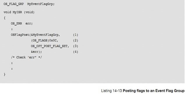
L14-13��1��ISR ���������
OSFlagPost()�ύ��־λ������������¼���־��ĵ�ַ��
L14-13(1) A task posts to the event flag group by calling
OSFlagPost(). Specify the desired event flag group to post by passing its
address. Of course, the event flag group must have been previously created.
L14-13��2���ڶ���������ʱ���־���е���Щλ��Ҫ�����û������
L14-13(2) The next argument specifies which bit(s) the
ISR (or task) will be setting or clearing in the event flag group.
L14-13
�� 3 ����ѡ�� OS_OPT_POST_FLAG_SET��OS_OPT_POST_FLAG_CLR��
�������Ϊ OS_OPT_POST_FLAG_SET���ڶ��������ύ��Ӧλ���� 1��
L14-13(3) Specify OS_OPT_POST_FLAG_SET or
OS_OPT_POST_FLAG_CLR.
If
specifying OS_OPT_POST_FLAG_SET, the bits specified in the second arguments
will set the corresponding bits in the event flag group. For example, if
MyEventFlagGrp.Flags contains 0x03, the code in Listing 14-13 will change
MyEventFlagGrp.Flags to 0x0F.
�������Ϊ OS_OPT_POST_FLAG_CLR���ڶ��������ύ��Ӧλ���� 0��
��������Ϊ OS_OPT_POST_NO_SCHED���������ѡ����ӡ�+��������ò���������������ύ��־λ�����������ȡ����ж���¼���־��ʱ��ͨ�������ã�����ʵ�ֽ������һ���ύʱ�������ȣ��������һ���ύʱ�����ø�ѡ���
If
specifying OS_OPT_POST_FLAG_CLR, the bits specified in the second arguments
will clear the corresponding bits in the event flag group. For example, if
MyEventFlagGrp.Flags contains 0x0F, the code in Listing 14-13 will change
MyEventFlagGrp.Flags to 0x03.
When
calling OSFlagPost() specify as an option (i.e., OS_OPT_POST_NO_SCHED) to not
call the scheduler. This means that the post is performed, but the scheduler is
not called even if a higher-priority task was waiting for the event flag group.
This allows the calling task to perform other post functions (if needed) and
make all the posts take effect simultaneously.
L14-13��4�����ݺ���ִ�н������һ��������š�
L14-13(4)
OSFlagPost() returns an error code based on the outcome of the call. If the
call was successful, err will contain OS_ERR_NONE. If not, the error code will
indicate the reason of the error (see Appendix A, ����C/OS-III API Reference
Manual�� on page 375 for a list of possible error codes for OSFlagPost().
ͨ���㲥�ź���ʵ�ֶ�����ͬ����ͨ�õķ�������Ȼ�ģ��ڵ� CPU ϵͳ�У�ͬһʱ��ֻ��ִ��һ������Ȼ��������������ͬʱ�������������������ͬ����
Synchronizing
the execution of multiple tasks by broadcasting to a semaphore is a commonly
used technique. It may be important to have multiple tasks start executing at
the same time. Obviously, on a single processor, only one task will actually
execute at one time.
Ȼ������Ҫͬ��һЩ����Ҫ���չ㲥���ź�����������������İ취�ǽ��ź�����ʱ���־��ͬʱ����ͬ������ͼ 14-11 ��ʾ���ٶ������������ȼ����ұ���������ȼ��͡�
However,
the start of their execution will be synchronized to the same time. This is
called a multiple task rendezvous. However, some of the tasks synchronized
might not be waiting for the semaphore when the broadcast is performed. It is
fairly easy to resolve this problem by combining semaphores and event flags, as
shown in Figure 14-11. For this to work properly, the task on the left needs to
have a lower priority than the tasks waiting on the semaphore.
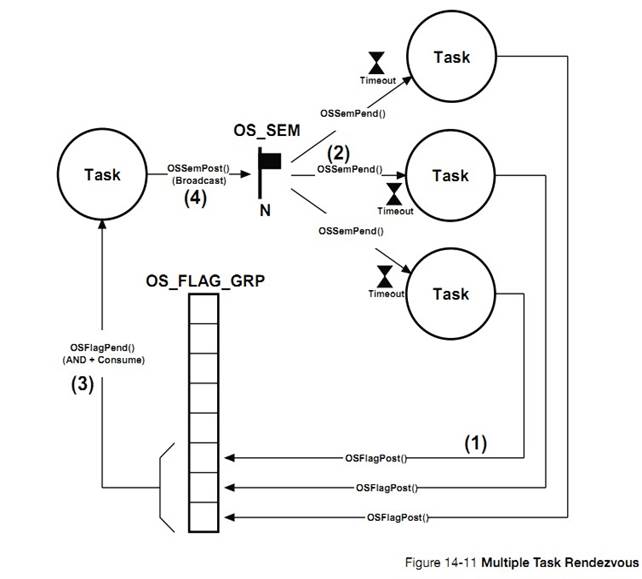
F14-11��1���ұߵ�ÿ��������Ҫ���¼���־���λ��Ӧ��
F14-11(1) Each task that needs to synchronize at the
rendezvous needs to set an event flag bit (and specify OS_OPT_POST_NO_SCHED).
F14-11��2���ұ�������ȴ��ź������ܱ�������
F14-11(2) The task needs to wait for the semaphore to be
signaled.
F14-11��3�����¼���־��������Ҫͬ���������Ӧλ������λ�����������ܹ㲥�ź�����
F14-11(3) The task that will be broadcasting must wait
for ��all�� of the event flags corresponding to each task to be set.
F14-11��4���������㲥�ź������ұ�����
F14-11(4) When all waiting tasks are ready, the task that
will synchronize the waiting task issues a broadcast to the semaphore.
�����ַ��������� ISR ����������һ���������������ź����������ź������¼���־�顣
Three
methods are presented to allow an ISR or a task to signal one or more tasks:
semaphores, task semaphores, and event flags.
�ź����������ź����ж����ź�������ֵ��ʾ���ź��������Ա����伸�Ρ��� ISR ��������Ҫ���һ������ʱ���Ƽ�ʹ�������ź�����Ϊ����Ա��ⶨ��һ���ⲿ�ź����Ҹ�Ϊ��Ч��
Both
semaphores and task semaphores contain a counter allowing them to perform
credit tracking and accumulate the occurrence of events. If an ISR or task
needs to signal a single task (as opposed to multiple tasks when the event
occurs), it makes sense to use a task semaphore since it prevents the user from
having to declare an external semaphore object.
Also,
task semaphore services are slightly faster (in execution time) than semaphores.
��������Ҫ��һ�������¼�ͬ��ʱʹ���¼���־�顣
Event
flags are used when a task needs to synchronize with the occurrence of one or
more events. However, event flags cannot perform credit tracking since a single
bit (as opposed to a counter) represents each event.
15����Ϣ����
��Щ���������� ISR ����һ����������ͨ�ţ�������Ϣ����������ҵ���ͨ�š����������ַ���ʵ������ͨ�ţ�ȫ�ֱ�����������Ϣ��
It
is sometimes necessary for a task or an ISR to communicate information to
another task. This information transfer is called inter-task communication.
Information can be communicated between tasks in two ways: through global data,
or by sending messages.
����� 13 �¡���Դ�����������ܡ����ʹ��ȫ�ֱ���������� ISR ����ȷ������ռ�ñ����������ֹ�� ISR Ƕ�ף���ô��ֻ�й��ж����ַ���������������������������乲���ñ�������ô����ͨ�����жϡ������������ź�����mutex �����ñ�����
As
seen in Chapter 13, ��Resource Management�� on page 209, when using global
variables, each task or ISR must ensure that it has exclusive access to
variables. If an ISR is involved, the only way to ensure exclusive access to
common variables is to disable interrupts. If two tasks share data, each can
gain exclusive access to variables either by disabling interrupts, locking the
scheduler, using a semaphore, or preferably, using a mutual-exclusion
semaphore.
��ע����ǣ�������ISR ͨ��ֻ��ͨ��ȫ�ֱ��������ȫ�ֱ����� ISR �ı䣬������֪��ȫ�ֱ������ı䣬���Ǹ�������ñ������� ISR ��������֪�ñ������ı䡣
Note
that a task can only communicate information to an ISR by using global
variables. A task is not aware when a global variable is changed by an ISR,
unless the ISR signals the task, or the task polls the contents of a variable
periodically.
��Ϣ���Ա����͵�ý�顪��Ϣ�����У�Ҳ����ֱ�ӷ���������Ϊ uC/OS-III ��ÿ�����������ڽ�����Ϣ���С�����������ȴ������Ϣʱ�ͽ�����Ϣ���͵��ⲿ����Ϣ���С���ֻ��һ������ȴ�����Ϣʱֱ�ӽ���Ϣ��������
Messages
can either be sent to an intermediate object called a message queue, or
directly to a task since in ��C/OS-III, each task has its own built-in message
queue. Use an external message queue if multiple tasks are to wait for
messages. Send a message directly to a task if only one task will process the
data received.
����ȴ���Ϣ����ʱ����ռ�� CPU��
When
a task waits for a message to arrive, it does not consume CPU time.
��Ϣ�а���һ��ָ�����ݵ�ָ�롢�����ݵĴ�С��ʱ�����������ָ�����ָ����������������һ����������Ȼ����Ϣ�ķ��ͷ�����Ϣ�Ľ��շ���Ӧ��֪����Ϣ�����������塣���仰˵�����շ�֪�����շ�����Ϣ�ĺ��塣
A
message consists of a pointer to data, a variable containing the size of the
data being pointed to, and a timestamp indicating when the message was sent.
The pointer can point to a data area or even a function. Obviously, the sender
and the receiver must agree as to the contents and the meaning of the message.
In other words, the receiver of the message will know the meaning of the
message received to be able to process it. For example, an Ethernet controller
receives a packet and sends a pointer to this packet to a task that knows how
to handle the packet.
��Ϣ�����ݣ������ݣ�ͨ��������������������Ϊ���͵������ݵĵ�ַ���������ݡ����仰˵�����ݲ��DZ����������������Ǹ����������ݵĵ�ַ�����������Լ�ȥ���ʡ�
The
message contents must always remain in scope since the data is actually sent by
reference instead of by value. In other words, data sent is not copied.
Consider using dynamically allocated memory as described in Chapter 17, ��Memory
Management�� on page 323. Alternatively, pass pointers to a global variable, a
global data structure, a global array, or a function, etc.
��Ϣ�������ں˶�����ʵ�ϣ����Է����������Ϣ���У�ֻҪ�������� RAM �㹻�Ļ�����
A
message queue is a kernel object allocated by the application. In fact, you can
allocate any number of message queues. The only limit is the amount of RAM
available.
ͨ����Ϣ�����û��������ܶ����飬��ͼ 15-1.Ȼ����ISR ��ֻ�ܵ���
OSQPost()��
There
are a number of operations that the user can perform on message queues,
summarized in Figure 15-1. However, an ISR can only call OSQPost(). A message
queue must be created before sending messages through it.
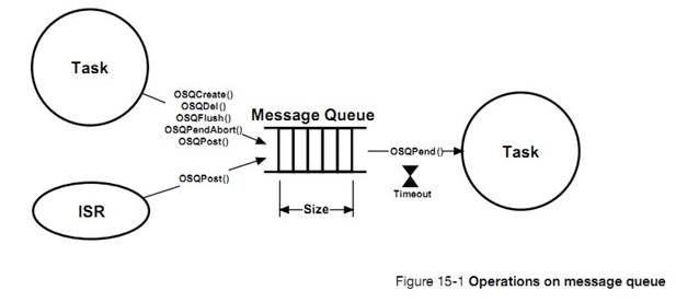
��Ϣ�����������ȳ�ģʽ��FIFO����Ȼ����uC/OS-III Ҳ���Խ�������Ϊ�����ȳ�ģʽ��LIFO����������� ISR ���ͽ�����Ϣ����һ������ʱ�������ȳ�ģʽ�Ƿdz����õģ�����������£��ý�����Ϣ�ƹ���Ϣ�����е�������Ϣ����Ϣ���еij��ȿ���������ʱ���á�
Message
queues are drawn as a first-in, first-out pipe (FIFO). However, with ��C/OS-III,
it is possible to post messages in last-in, first-out order (LIFO). The LIFO
mechanism is useful when a task or an ISR must send an ��urgent�� message to a
task. In this case, the message bypasses all other messages already in the
message queue. The size of the message queue is configurable at run time.
����ͼ�����������Ե�ɳ©��ʾ������������õȴ����ޡ��������û���ڹ涨ʱ���ڽ��յ�����Ϣ��uC/OS-III �᷵��һ��������ű�ʾ������������Ϊ���յ���Ϣ�����ǵȴ���ʱ��
The
small hourglass close to the receiving task indicates that the task has an
option to specify a timeout. This timeout indicates that the task is willing to
wait for a message to be sent to the message queue within a certain amount of
time. If the message is not sent within that time, ��C/OS-III resumes the task
and returns an error code indicating that the task was made ready to run
because of a timeout, and not because the message was received. It is possible
to specify an infinite timeout and indicate that the task is willing to wait
forever for the message to arrive.
��Ϣ�����д���˵ȴ�����Ϣ������������������Ϣ�����еȴ���Ϣ����ͼ 15-2 ��ʾ����һ����Ϣ�����͵���Ϣ����ʱ���ȴ�����Ϣ�ĸ����ȼ�������������Ϣ����Ϣ�����߿��Թ㲥�����Ϣ����Ϣ�����е�������������������£�������յ���Ϣ�������ȼ�������Ϣ���������ȼ�������uC/OS-III �ͻ��л�����������ȼ�������ע�⣺����ÿ��������Ҫ���õȴ����ޣ���Щ���������Ҫ��Զ�ȴ������Ϣ��
The
message queue also contains a list of tasks waiting for messages to be sent to
the message queue. Multiple tasks can wait on a message queue as shown in
Figure 15-2. When a message is sent to the message queue, the highest priority
task waiting on the message queue receives the message. Optionally, the sender
can broadcast a message to all tasks waiting on the message queue. In this
case, if any of the tasks receiving the message from the broadcast has a higher
priority than the task sending the message (or interrupted task, if the message
is sent by an ISR), ��C/OS-III will run the highest-priority task that is
waiting. Notice that not all tasks must specify a timeout; some tasks may want
to wait forever.
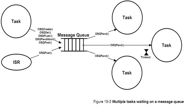
���ٻ�����������ͬʱ��һ����Ϣ�����еȴ�����Ϊ������uC/OS-III ���������ڽ���һ����Ϣ���С��û�����ֱ�ӷ�����Ϣ���������ͨ���ⲿ��Ϣ���С�������Բ������˴��룬���ṩ��Ч�ʡ�ÿ�������ڽ�һ����Ϣ���У���ͼ 15-3 ��ʾ��
It
is fairly rare to find applications where multiple tasks wait on a single
message queue. Because of this, a message queue is built into each task and the
user can send messages directly to a task without going through an external
message queue object. This feature not only simplifies the code but, is also
more efficient than using a separate message queue object. The message queue
that is built into each task is shown in Figure 15-3.
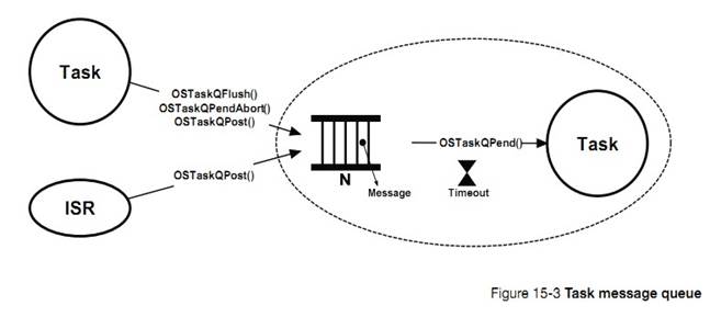
uC/OS-III
����������Ϣ������صķ������� OSTask???()��ͷ�ġ����� OS_CFG.H �е� OS_CFG_TASK_EN ʹ���������Ϣ���з�����������Ϣ������صĴ����� OS_TASK.C �С�
Task
message queue services in ��C/OS-III start with the OSTaskQ???() prefix, and
services available to the application programmer are described in Appendix A,
����C/OS-III API Reference Manual�� on page 375. Setting OS_CFG_TASK_EN in
OS_CFG.H enables task message queue services. The code for task message queue
management is found in OS_TASK.C.
Use
this feature if the code knows which task to send the message(s) to. For
example, if receiving an interrupt from an Ethernet controller, send the
address of the received packet to the task that will be responsible for
processing the received packet.
�����������ͨ��������Ϣ����ͬ������ͼ 15-4 ��ʾ�������˫��ͨ�ţ��������������ܻ������Ϣ���Է��������� ISR �䲻��˫��ͨ�ţ���Ϊ ISR ��������Ϣ�����еȴ���
Two
tasks can synchronize their activities by using two message queues, as shown in
Figure 15-4. This is called a bilateral rendezvous and works the same as with
semaphores except that both tasks may send messages to each other. A bilateral
rendezvous cannot be performed between a task and an ISR since an ISR cannot
wait on a message queue.
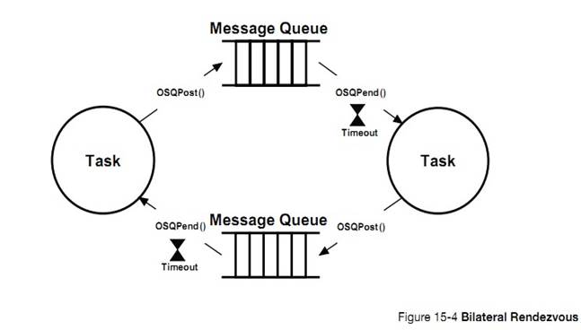
��������Ϣ���ж�����ʼ��Ϊ�ա�����ߵ�����Լ����ʱ�����ͻᷢ����Ϣ��������Ϣ���в��ڵײ���Ϣ�����еȴ���Ϣ�����Ƶģ����ұߵ�����ij��ʱ�̣����ͻᷢ����Ϣ���ײ���Ϣ���У����ڶ�����Ϣ�����еȴ���Ϣ��
In a
bilateral rendezvous, each message queue holds a maximum of one message. Both
message queues are initially created empty. When the task on the left reaches
the rendezvous point, it sends a message to the top message queue and waits for
a message to arrive on the bottom message queue. Similarly, when the task on
the right reaches its rendezvous point, it sends a message to the message queue
on the bottom and waits for a message to arrive on the top message queue.
ͼ 15-5 ��ʾ�������ʵ��˫��ͨ��
Figure
15-5 shows how to use task-message queues to perform a bilateral rendezvous.
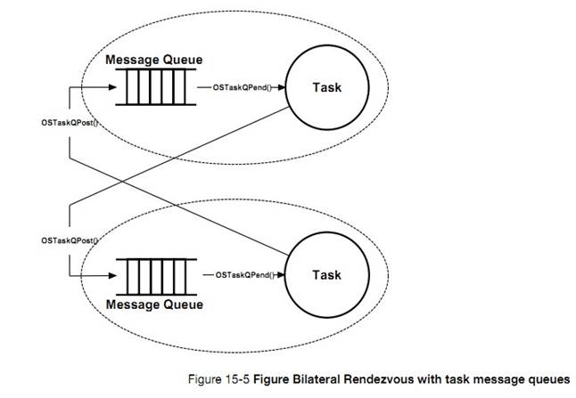
������ͨ�ž���ͨ�������� A �д������ݸ����� B��Ȼ��������
A ������������Ҫʱ�䣬������ B �����ڸ����ݱ��������ܳ�ʱ��Ž��յ������ݡ����仰˵������������ȼ���������ռ������ B����ô���� A ���������Ϣ�����е����ݾͿ��ܱ�����������������һ�ַ������ڴ�������������������ͼ 15-6 ��ʾ
Task-to-task
communication often involves data transfer from one task to another. One task
produces data while the other consumes it. However, data processing takes time
and consumers might not consume data as fast as it is produced. In other words,
it is possible for the producer to overflow the message queue if a
higher-priority task preempts the consumer. One way to solve this problem is to
add flow control in the process as shown in Figure 15-6.
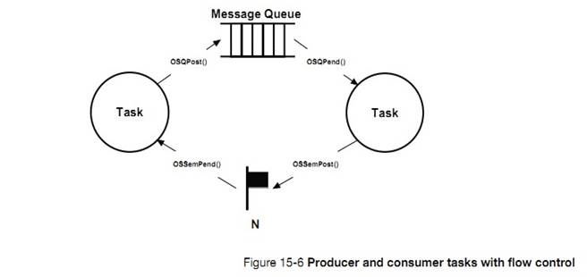
�����ʹ����һ���ź�������ֵ����ֵ��ʼ��Ϊ���� B ����Ϣ���г��ȡ�
Here,
a counting semaphore is used, initialized with the number of allowable messages
that can be sent by the consumer. If the consumer cannot queue more than 10
messages, the counting semaphore contains a count of 10.
���б� 15-1 ��ʾ������ A �ڷ�����Ϣ������ B ֮ǰ�������ź��������� B ��Ϣ���еĿ�����Ϊ���٣��ź�������ֵ��Ϊ���١�
As
shown in the pseudo code of Listing 15-1, the producer must wait on the
semaphore before it is allowed to send a message. The consumer waits for
messages and, when processed, signals the semaphore.
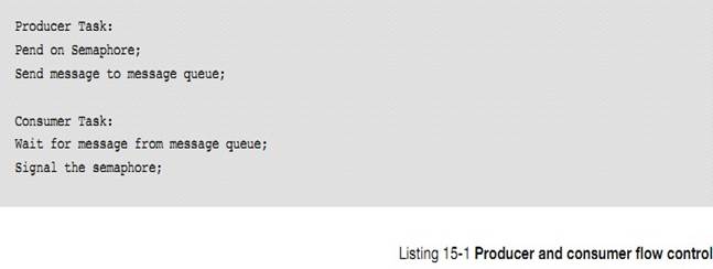
���������Ϣ���к��ź�������һ��ʹ�ã����� 14 �¡�ͬ��������ʵ���������ƽ��Ǽģ���ͼ 15-7 ��ʾ������������£���Ҫ���� OSTaskSemSet()������������ B ���ź�������ֵΪ���� B ��Ϣ���е���Ϣ������
Combining
the task message queue and task semaphores (see Chapter 14, ��Synchronization��
on page 251), it is easy to implement flow control as shown in Figure 15-7. In
this case, however, OSTaskSemSet() must be called immediately after creating
the task to set the value of the task semaphore to the same value as the
maximum number of allowable messages in the task message queue.
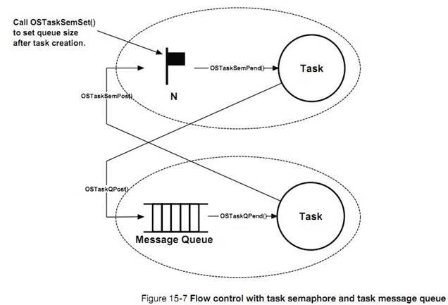
��Ϣͨ��ָ��ṹ�塢����������ȡ�Ȼ�������ݱ��뱻�������������ṹ�塢���������飩��ֱ����������ɶ���Щ���ݵIJ�������Ϣһ�������ͣ������߾Ͳ��ܷ��ʱ����͵���Ϣ�������������ݡ��⿴��������Ȼ�������������ǡ�
The
messages sent typically point to data structures, variables, arrays, tables,
etc. However, it is important to realize that the data must remain static until
the receiver of the data completes its processing of the data. Once sent, the
sender must not touch the sent data. This seems obvious, however it is easy to
forget.
ͨ�� uC/OS-III �еķ��������������� 17 �¡��ڴ����������̬�ط���ͻ����ڴ�����ڴ�����Щ���ݣ���Ϣ�������������ݣ���ͼ 15-8 ��ʾ��һ�����ӣ��ٶ�һ������ͨ��ij��Э�鷢���ֽ����ݰ���UART������������£����ݰ��Ŀ�ʼ�ֽںͽ����ֽ�Ӧ�ö�һ���ġ�
One
possibility is to use the fixed-size memory partition manager provided with
��C/OS-III (see Chapter 17, ��Memory Management�� on page 323) to dynamically
allocate and free memory blocks used to pass the data. Figure 15-8 shows an
example. For sake of illustration, assume that a device is sending data bytes
to the UART in packets using a protocol. In this case, the first byte of a
packet is unique and the end-of-packet byte is also unique.
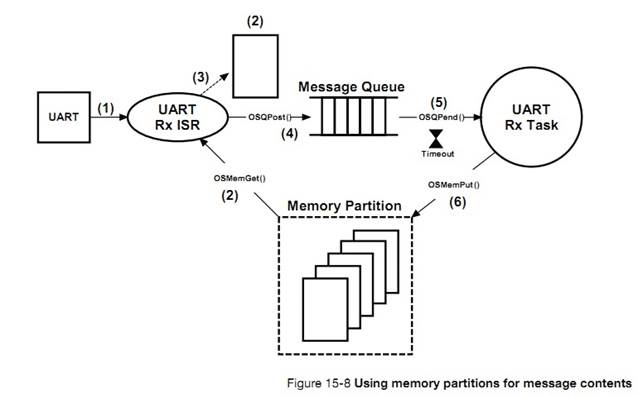
F15-8��1�����UART ���յ���ʼ�ֽڲ��жϡ�
F15-8(1) Here, a UART generates an interrupt when
characters are received.
F15-8��2���б� 15-2 ����ʾ�� UART �� ISR ���롣ISR �� UART �ж�ȡ���յ������ݲ��۲����Ƿ�Ϊ���ݰ��Ŀ�ʼ�ֽڡ�����ǣ��ͻ��һ���ڴ�顣
F15-8(2) The pseudo-code in Listing 15-2 shows
what the UART ISR code might look like. There are a lot of details omitted for
sake of simplicity. The ISR reads the byte received from the UART and sees if
it corresponds to a start of packet. If it is, a buffer is obtained from the
memory partition.
F15-8��3�����յ������ݱ������ڴ���С�
F15-8(3) The received byte is then placed in the
buffer.
F15-8��4����������Ľ����ֽڣ����ύ����ڴ��ĵ�ַ����Ϣ���У��Ա���������������հ���
F15-8(4) If the data received is an end-of-packet
byte, simply post the address of the buffer to the message queue so that the
task can process the received packet.
F15-8��5����������Ϣʹ UART �������������Ϊ������ȼ����� uC/OS-III ��ִ���� ISR ֮��ͻ���ת���������������Ϣ�����л�����ݰ���ע����ǣ�OSQPend()�����ú����ݰ����ֽ�����ʱ��������˸���Ϣ������ʱ��ʱ�������
F15-8(5) If the message sent makes the UART task
the highest priority task, ��C/OS-III will switch to that task at the end of the
ISR instead of returning to the interrupted task. The task retrieves the packet
from the message queue. Note that the OSQPend() call also returns the number of
bytes in the packet and a time stamp indicating when the message was sent.
F15-8��6����������������ݰ���ͨ������ OSMemPut()������ڴ���ͷš�
F15-8(6) When the task is finished processing the
packet, the buffer is returned to the memory partition it came from by calling
OSMemPut().
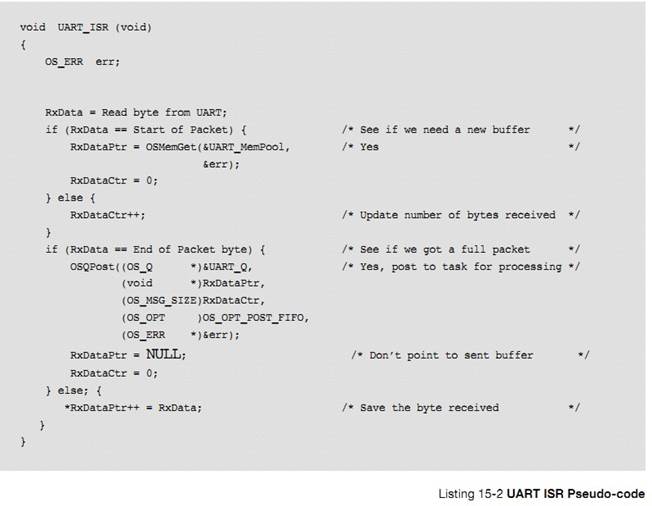
�� 15-1 �ǹ�����Ϣ���к������ܽᡣ�����¼ A
Table
15-1 shows a summary of message-queue services available from ��C/OS-III. Refer
to Appendix A, ����C/OS-III API Reference Manual�� on page 375 for a full
description on their use.
|
������
|
����
|
|
OSQCreate()
|
����һ����Ϣ����
Create a message queue.
|
|
OSQDel()
|
ɾ��һ����Ϣ����
Delete a message queue.
|
|
OSQFlush()
|
���һ����Ϣ����
Empty the message queue.
|
|
OSQPend()
|
����ȴ���Ϣ
Wait for a message.
|
|
OSQPendAbort()
|
�����ٵȴ�����Ϣ
Abort waiting for a message.
|
|
OSQPost()
|
�ύһ����Ϣ����Ϣ����
Send a message through a message queue.
|
�� 15-1 ��Ϣ���е� API �ܽ�
�� 15-2 ����������Ϣ���к������ܽᣬ�����¼ A��
Table
15-2 is a summary of task message queue services available from ��C/OS-III.
Refer to Appendix A, ����C/OS-III API Reference Manual�� on page 375, for a full
description on how to their use.
|
������
|
����
|
|
OSTaskQPend()
|
�ȴ�һ����Ϣ
Wait for a message.
|
|
OSTaskQPendAbort()
|
�����ٵȴ�����Ϣ
Abort the wait for a message.
|
|
OSTaskQPost()
|
����һ����Ϣ������
Send a message to a task.
|
|
OSTaskQFlush()
|
��������Ϣ����
Empty the message queue.
|
�� 15-2 ������Ϣ���е� API �ܽ�
ͼ 15-9 ��ʾ��ͨ����Ϣ����������ת�ֵ���ת���ʡ�
Figure
15-9 shows an example of using a message queue when determining the speed of a
rotating wheel.
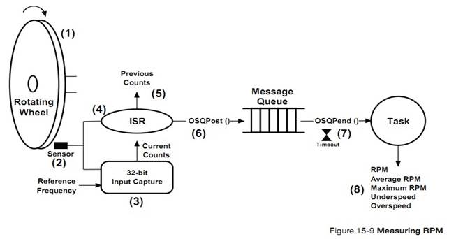
F15-9��1��������Ŀ���Dz�����ת�ֵ���ת���ʡ�
F15-9(1) The goal is to measure the RPM of a
rotating wheel.
F15-9��2�������������ڲ�������ת�ֵ����ʡ��ֵ���Χ�кܶ�С�ף����Ǹ��������
F15-9(2) A sensor is used to detect the passage of
a hole in the wheel. In fact, to receive additional resolution, the wheel could
contain multiple holes that are equally spaced.
F15-9��3��32 λ�����벶��Ĵ������ڲ���ÿ���ж�ʱ�� CPU ����ֵ��Ҳ����ʱ�������
F15-9(3) A 32-bit input capture register is used
to capture the value of a free-running counter when the hole is detected.
F15-9��4����һ����ʱ�жϲ�����ISR ��ȡ��ǰ�IJ���Ĵ���ֵ����ȥ��ǰ�IJ���ֵ������֪����ת�����ʡ�
F15-9(4) An interrupt is generated when the hole
is detected. The ISR reads the current count of the input capture register and
subtracts the value of the previous capture to receive the time it took for one
rotation (assuming only a single hole).
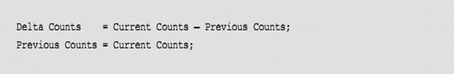
F15-9��5��Delta ֵ�����͵���Ϣ���С���Ϊ��Ϣʵ������һ��ָ�룬������ָ���� 32 λ�ģ�ֱ�ӽ� Delta ֵ�浽���ָ���б����͵���Ϣ���С�������ȫ�ķ����Ƿ���һ���ڴ�鲢�� Delta ֵ�����ڴ�鲢���ڴ���ַ������Ϣ��
F15-9(5) The delta counts are sent to a message
queue. Since a message is actually a pointer, if the pointer is 32-bits wide on
the processor in use, simply cast the 32-bit delta counts to a pointer and send
this through the message queue. A safer and more portable approach is to
dynamically allocate storage to hold the delta counts using a memory block from
��C/OS-III��s memory management services (see Chapter 17, ��Memory Management�� on
page 323) and send the address of the allocated memory block.
F15-9��6������Ϣ�����ͺ��������ѣ�������ÿ���ӵ���ת���ʣ�
F15-9(6) When the message is sent, the RPM
measurement task wakes up and computes the RPM as follows:
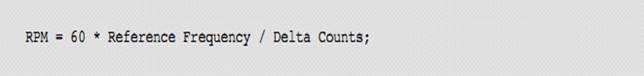
�û����Ը��������������������������Ϊ��ʱ�������ѡ�����ܾͱ�����ת�ֵ�����Ϊ 0.
The
user may specify a timeout on the pend call and the task will wake up if a
message is not sent within the timeout period. This allows the user to easily
detect that the wheel is not rotating and therefore, the RPM is 0.
F15-9��7��������Ҳ���Լ���ƽ����ת���ʣ������ת���ʵȴ���
F15-9(7)
Along with computing RPM, the task can also compute average RPM, maximum RPM,
and whether the speed is above or below thresholds, etc.
���������������һЩ��Ȥ�����顣��һ��ISR �dz��̣���ȡ����ֵ���� Delta ֵ�������ڶ����������������ʱ���Ϳ���֪����ת�ֱ�ֹͣ�ˡ�����������л���������һЩ���������������ת���Ƿ�ת�ù��������������Ը�֪��ת�������������
A
few interesting things are worth noting about the above example. First, the ISR
is very short; read the input capture and post the delta counts to the task to
accomplish the time-consuming math. Second, with the timeout on the pend, it is
easy to detect that the wheel is stopped. Finally, the task can perform
additional calculations and can further detect such errors as the wheel
spinning too fast or too slow. In fact, the task can notify other tasks about
these errors, if needed.
�б� 15-3 ��ʾ���������Ϣ���в�����ת���ʡ�
Listing
15-3 shows how to implement the RPM measurement example using ��C/OS-III��s
message queue services. Some of the code is pseudo-code, while the calls to
��C/OS-III services are actual calls with their appropriate arguments.
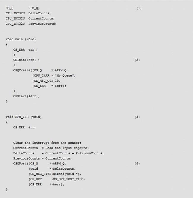
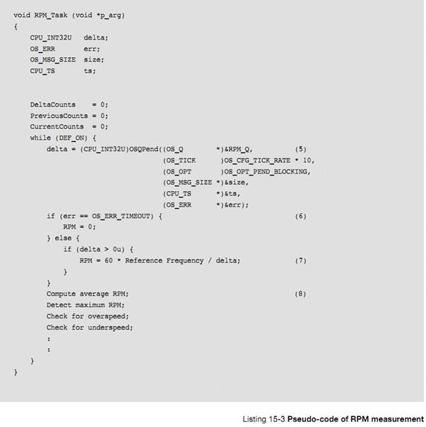
L15-3��1����Ϣ���б����塣
L15-3(1) Variables are declared. Notice that it is
necessary to allocate storage for the message queue itself.
L15-3��2������ OSInit()������Ϣ���С�
L15-3(2) Call OSInit() and create the message
queue before it is used. The best place to do this is in startup code.
L15-3��3��ISR ����������жϲ���ȡ����Ĵ�����ֵ���� ISR �м��� Delta ����ֵ��Ҳ����ֱ�ӷ��Ͳ���ֵ�����ڲ��������м��� Delta ֵ��Ȼ������������Ǻܿ�ģ��������ӵ� ISR ʱ��ɺ��Բ��ơ�
L15-3(3) The RPM ISR clears the sensor interrupt
and reads the value of the 32-bit input capture. Note that it is possible to
read RPM if there is only a 16-bit input capture. The problem with a 16-bit
input capture is that it is easy for it to overflow, especially at low RPMs.
The
RPM ISR also computes delta counts directly in the ISR. It is just as easy to
post the current counts and let the task compute the delta. However, the
subtraction is a fast operation and does not significantly increase ISR
processing time.
L15-3��4���� Delta ֵ���͵���������ִ����Ӧ���㡣ע����ǣ�����Ϣ��������ʱ���������ύ�ͻᵼ���������Ϣ�������ύʱ�ͻ��������������ܲ��ң�����ͨ���������ƽ�����������Ϊ��Ϣ���� ISR �б��ύ�ġ�
L15-3(4) Send the delta counts to the RPM task,
responsible for computing the RPM and perform additional computations. Note
that the message gets lost if the queue is full when the user attempts to post.
This happens if data is generated faster than it is processed. Unfortunately,
it is not possible to implement flow control in the example because it is
dealing with an ISR.
L15-3��5����������ȴ����� ISR �е���Ϣ�����������������˵ȴ����ޡ������������˵ȴ�����Ϊ 10 �롣���� ts ��������Ϣ���ύʱ��ʱ�����ͨ�� OS_TS_GET()��õ�ǰ��ʱ���������Ϣ����Ӧʱ����ܼ��㣺
L15-3(5) The RPM task starts by waiting for a
message from the RPM ISR by pending on the message queue. The third argument
specifies the timeout. In this case, ten seconds worth of timeout is specified.
However, the value chosen depends on the requirements of an application.
Also
notice that the ts variable contains the timestamp of when the post was
completed. Determine the time it took for the task to respond to the message
received by calling OS_TS_GET(), and subtract the value of ts:
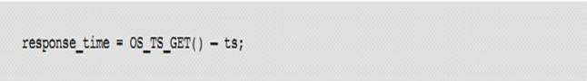
L15-3��6���ȴ���ʱ���ٶ�����ת��ֹͣ��ת����
L15-3(6) If a timeout occurs, assume the wheel is
no longer spinning.
L15-3��7��������ת���ʡ�
L15-3(7) The RPM is computed from the delta counts
received, and from the reference frequency of the free-running counter.
L15-3��8��������һЩ��������ʵ�ϣ��ڼ�������������Ϣ���Ա����������������磬����ת���ʺܿ죬��������Ϳ�������ת�ּ��١�
L15-3(8) Additional computations are performed as
needed. In fact, messages can be sent to different tasks in case error
conditions are detected. The messages would be processed by the other tasks.
For example, if the wheel spins too fast, another task can initiate a shutdown
on the device that is controlling the wheel speed.
���б� L15-4������������У��� OSTaskQPost()�� OSTaskQPend() ���� OSQPost()�� OSQPend()�����뽫������Ҳ���Ҫ����һ���ⲿ��Ϣ���С�Ȼ������������������ʱ���ͱ�����������Ϣ���д�С���ڱ���ʱ���� OS_CFG_TASK_Q_EN Ϊ 1��ʹ���ⲿ��Ϣ���к������ڲ���Ϣ���е��������½��ܡ�
In
Listing 15-4, OSQPost() and OSQPend() are replaced with OSTaskQPost() and
OSTaskQPend() for the RPM measurement example. Notice that the code is slightly
simpler to use and does not require creating a separate message queue object.
However, when creating the RPM task, it is important to specify the size of the
message queue used by the task and compile the application code with
OS_CFG_TASK_Q_EN set to 1. The differences between using message queues and the
task��s message queue will be explained.
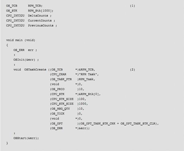
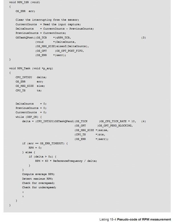
L15-4��1������� OS_TCB Ҳ���Խ�����Ϣ��
L15-4(1) Instead of declaring a message queue, it
is important to know the OS_TCB of the task that will be receiving messages.
L15-4��2����������������������Ϣ���еĴ�СΪ 10����Ȼ����ʵʱϵͳ����ò�Ҫ����ֵ�̶�����������Ϊ��˵��������ֵ�̶�Ϊ
10��
L15-4(2) The RPM task is created and a queue size of
10 entries is specified. Of course, hard-coded values should not be specified
in a real application, but instead, use #defines. Fixed numbers are used here
for sake of illustration.
L15-4��3��ISR ֱ�ӽ���Ϣ��������
L15-4(3) Instead of posting to a message queue,
the ISR posts the message directly to the task, specifying the address of the
OS_TCB of the task. This is known since the OS_TCB is allocated when creating
the task.
L15-4��4����������ͨ������ OSTaskQPend()�ȴ� ISR ���͵���Ϣ������һ���ڲ��ĵ��ã�����û��Ҫ���� OS_TCB �ĵ�ַ���ڶ����������õȴ����ޡ�
L15-4(4) The RPM task starts by waiting for a
message from the RPM ISR by calling OSTaskQPend(). This is an inherent call so
it is not necessary to specify the address of the OS_TCB to pend on as the
current task is assumed. The second argument specifies the timeout. Here, ten
seconds worth of timeout is specified, which corresponds to 6 RPM.
��Ϣ������һ���÷���ͼ 15-10 ��ʾ������������������������� ISR �������Ĵ�����������磬����������ת����ת���ʹ��죬��������Ϣ��������������������������Ӧ�IJ�����
Another
interesting use of message queues is shown in Figure 15-10. Here, a task (the
server) is used to monitor error conditions that are sent to it by other tasks
or ISRs (clients). For example, a client detects whether the RPM of the
rotating wheel has been exceeded, another client detects whether an
over-temperature exists, and yet another client detects that a user pressed a
shutdown button. When the clients detect error conditions, they send a message
through the message queue. The message sent indicates the error detected, which
threshold was exceeded, the error code that is associated with error
conditions, or even suggests the address of a function that will handle the
error, and more.
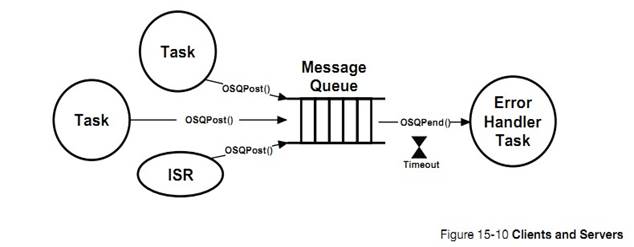
��Ϣ���ĸ�������ɣ�ָ����һ����Ϣ��ָ�롢���ڱ�������Ϣ��ָ�����ݵĴ�С�ı����������Ϣ���һ�α��ύ��ʱ����ı�������Ϣ�а���һ��ָ��ʵ�����ݵ�ָ�롣��ͼ 15-11 ��ʾ
As
previously described, a message consists of a pointer to actual data, a
variable indicating the size of the data being pointed to and a timestamp
indicating when the message was actually sent. When sent, a message is placed
in a data structure of type OS_MSG, shown in Figure 15-11.
��Ϣ�����ߺͽ����߶���֪����Ϣ�����ݵĽṹ��Ϊ��Щ��ͨ�� uC/OS-III �� API ���������ˡ�
The
sender and receiver are unaware of this data structure since everything is
hidden through the APIs provided by ��C/OS-III.
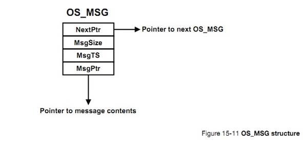
uC/OS-III
ά��һ����Ϣ�ء���Ϣ�صĴ�Сͨ�� OS_CFG_APP.H�е�
OS_CFG_MSG_POOL_SIZE ���á��� uC/OS-III ����ʼ��ʱ����Ϣ�ͻ��Ե����б�����ʽ����������ͼ 15-12��ע���������б��ɽṹ�� OS_MSG_POOL ������������ 3 �����֣�.NextPtr ָ�����Ϣ�б���.NbrFree �����˸ö��еĿ�����Ϣ����.NbrUsed �����˸ö������ѱ�ʹ�õ���Ϣ����
��C/OS-III
maintains a pool of free OS_MSGs. The total number of available messages in the
pool is determined by the value of OS_CFG_MSG_POOL_SIZE found in OS_CFG_APP.H.
When ��C/OS-III is initialized, OS_MSGs are linked in a single linked list as
shown in Figure 15-12. Notice that the free list is maintained by a data
structure of type OS_MSG_POOL, which contains three fields: .NextPtr, which
points to the free list; .NbrFree, which contains the number of free OS_MSGs in
the pool; and finally .NbrUsed, which contains the number of OS_MSGs allocated
to application.
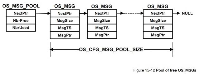
��Ϣ�������ɽṹ�� OS_MSG_Q ���ƣ���ͼ 15-13
Messages
are queued using a data structure of type OS_MSG_Q, as shown in Figure 15-13.
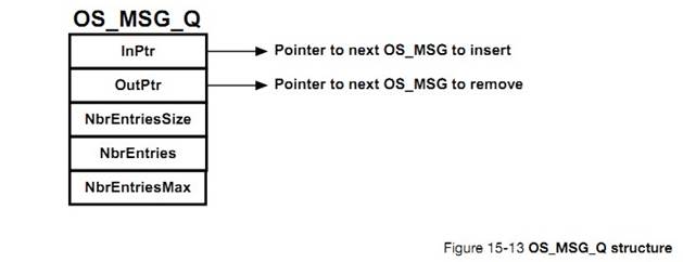
.InPtr ָ����һ����Ҫ�����뵽���е���Ϣ��
.InPtr This field contains a pointer to where
the next OS_MSG will be inserted in the queue. In fact, the OS_MSG will be
inserted ��after�� the OS_MSG pointed to.
.OutPtr ָ����һ����Ҫ���ͷŵ���Ϣ��
.OutPtr This field contains a
pointer to where the next OS_MSG will be extracted.
.NbrEntriesSize
�����˸ö������ܽ��ܵ������Ϣ�������������������з�����Ϣ����Ϣ�����ᱻ���롣
.NbrEntriesSize This field contains the maximum number of
OS_MSGs that the queue will hold. If an application attempts to send a message
and the .NbrEntries matches this value, the queue is considered to be full and
the OS_MSG will not be inserted.
.NbrEntries ��ǰ�����е���Ϣ��
.NbrEntries This field contains the
current number of OS_MSGs in the queue.
.NbrEntriesMax
��¼�˵�ĿǰΪֹ�����д�ŵ������Ϣ����
.NbrEntriesMax This field contains the highest number of
OS_MSGs existing in the queue at any given time.
uC/OS-III
����һЩ�������ڲ��ݿ��еĶ��к���Ϣ�����磺OS_MsgQPut()����Ϣ���뵽 OS_MSG_Q��OS_MsgQGet()�� OS_MSG_Q �еõ�һ����Ϣ��OS_MsgQFreeAll()������ OS_MSQ_Q �е���Ϣ�ͷŻ���Ϣ���С�OS_MSG.C �е�����һЩ OS_MsgQ??()�ڳ�ʼ��ʱʹ�á�
A
number of internal functions are used by ��C/OS-III to manipulate the free list
and messages. Specifically, OS_MsgQPut() inserts an OS_MSG in an OS_MSG_Q,
OS_MsgQGet() extracts an OS_MSG from an OS_MSG_Q, and OS_MsgQFreeAll() returns
all OS_MSGs in an
OS_MSG_Q
to the pool of free OS_MSGs. There are other OS_MsgQ??() functions in OS_MSG.C
that are used during initialization.
ͼ 15-14 ��ʾ���� 4 ����Ϣ��
OS_MSG_Q��
Figure
15-14 shows an example of an OS_MSG_Q when four OS_MSGs are inserted.
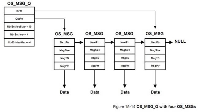
OS_MSG_Q
ͨ�����������ֽṹ���ڣ�OS_Q �� OS_TCB������һ�� OS_Q ʱ���ڽ�һ�� OS_MSG_Q�������� OS_CFG.H �е� OS_CFG_TASK_Q_EN Ϊ 1 ʱ��ÿ�����������ڽ�����Ϣ���С���ͼ 15-15 ��ʾ��
OS_MSG_Qs
are used inside two additional data structures: OS_Q and OS_TCB. Recall that an
OS_Q is declared when creating a message queue object. An OS_TCB is a task
control block and, as previously mentioned, each OS_TCB can have its own
message queue when the configuration constant OS_CFG_TASK_Q_EN is set to 1 in
OS_CFG.H. Figure 15-15 shows the contents of an OS_Q and partial contents of an
OS_TCB containing an OS_MSG_Q. The OS_MSG_Q data structure is shown as an
��exploded view�� to emphasize the structure within the structure.
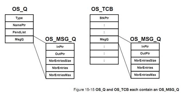
������� ISR ������Ϣ����һ������ʱ��ͨ����Ϣ�����Ǻ���Ч�ķ����������͵���Ϣ�е����ݱ��뱻�洢����Ϊ���͵������ݵ�ַ������ʵ�ʵ����ݡ�
Message
queues are useful when a task or an ISR is to send data to another task. The
data sent must remain in scope as it is actually sent by reference instead of
by value. In other words, the data sent is not copied.
�����ڵȴ���Ϣ��ʱ��ռ�� CPU��
The
task waiting for the data will not consume CPU time while waiting for a message
to be sent to it.
ʹ�������ڲ�����Ϣ��ջ��Ϊ��Ч�������� OS_CFG.H �е�OS_CFG_TASK_Q_EN Ϊ 1 ʱʹ�������ڲ���Ϣ���С�
If
it is known which task is responsible for servicing messages sent by producers,
use task message queue (i.e., OSTaskQ???()) services since they are simple and
fast. Task message queue services are enabled when OS_CFG_TASK_Q_EN is set to 1
in OS_CFG.H.
����������ȴ�ͬһ����Ϣ�����е���Ϣ������һ�� OS_Q �����������ȴ�����Ϣ���͵� OS_Q �С��ر�ģ����Թ㲥��Ϣ����������Ϣ�����еȴ����������� OS_CFG.H �е� OS_CFG_Q_EN Ϊ1 ������Ϣ���з���
If
multiple tasks must wait for messages from the same message queue, allocate an
OS_Q and have the tasks wait for messages to be sent to the queue. Alternatively,
broadcast special messages to all tasks waiting on a message queue. Regular
message queue services are enabled when OS_CFG_Q_EN is set to 1 in OS_CFG.H.
��Ϣͨ���ṹ�� OS_MSG���� uC/OS-III ����Ϣ���л�ã������͡�������Ϣ���еĴ�С������Ϣ�صĴ�С��
Messages
are sent using an OS_MSG data structure obtained by ��C/OS-III from a pool. Set
the maximum number of messages that can be sent to a message queue, or as many
messages as are available in the pool.
16������������
���½� 10��������С��н����˶��������εȴ�һ���ں˶������ź�����mutex���¼���־�顢��Ϣ���С�������½��У�����������ȴ��������Ȼ����uC/OS-III ֻ����ͬʱ�ȴ�����ź�������Ϣ���С����仰˵������ͬʱ�ȴ�����¼���־��� mutex��
In
Chapter 10, ��Pend Lists (or Wait Lists)�� on page 177 we saw how multiple tasks
can pend (or wait) on a single kernel object such as a semaphore, mutual
exclusion semaphore, event flag group, or message queue. In this chapter, we
will see how tasks can pend on multiple objects. However, ��C/OS-III only allows
for pend on multiple semaphores and/or message queues. In other words, it is
not possible to pend on multiple event flag groups or mutual exclusion
semaphores.
��ͼ 16-1 ��ʾ���������ͬʱ�ȴ�����ź�������Ϣ���С�������յ�һ���ź�������Ϣ�ͻᱻ����������ͨ������ OSPendMulti() �ȴ����������ʹ���õȴ�ʱ�ޡ����ʱ��Ӧ�����еĶ��������ʱ����û���յ�һ����������ͻ᷵��һ��������ű�ʾ�ȴ���ʱ��
As
shown in Figure 16-1, a task can pend on any number of semaphores or message
queues at the same time. The first semaphore or message queue posted will make
the task ready to run and compete for CPU time with other tasks in the ready
list. As shown, a task pends on multiple objects by calling OSPendMulti() and
specifies an optional timeout value. The timeout applies to all of the objects.
If none of the objects are posted within the specified timeout, the task
resumes with an error code indicating that the pend timed out.
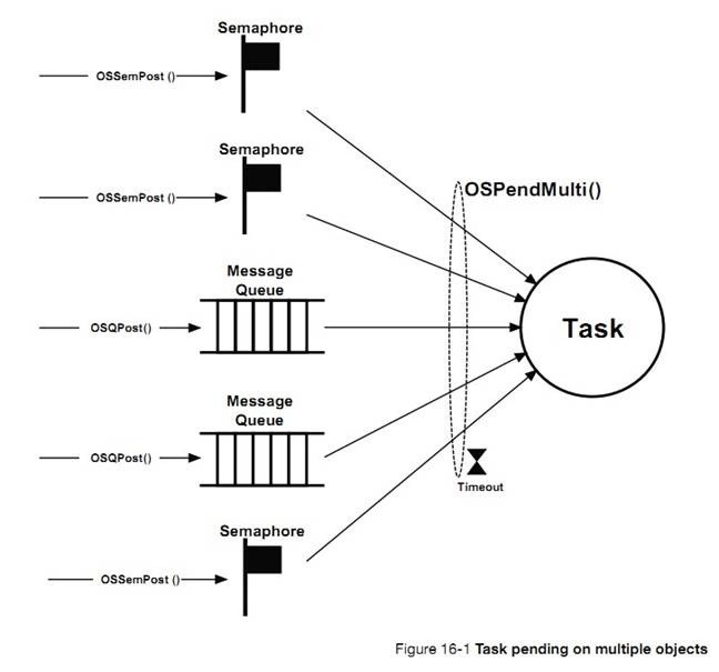
�б� 16-1 ��ʾ�� OSPendMulti()��ԭ�ͣ�ͼ 16-2 ��ʾ��һ����������Ϊ OS_PEND_DATA �����顣
Listing
16-1 shows the function prototype of OSPendMulti() and Figure 16-2 exhibits an
array of OS_PEND_DATA elements.
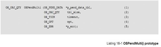
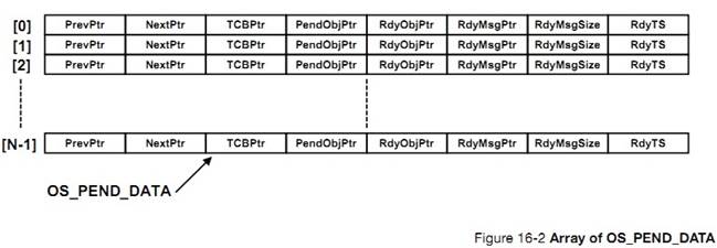
L16-1��1��OSPendMulti �ĵ�һ����������������Ϊ OS_PEND_DATA �����顣����Ĵ�С�������������ȴ����ں˶����������磬�������Ҫ�ȴ� 3 ���ź����� 2 ����Ϣ����ô����Ĵ�СΪ 5��
L16-1(1)
OSPendMulti() is passed an array of OS_PEND_DATA elements. The caller must
instantiate an array of OS_PEND_DATA. The size of the array depends on the
total number of kernel objects that the task wants to pend on. For example, if
the task wants to pend on three semaphores and two message queues then the
array contains five OS_PEND_DATA elements as shown below:
ÿ������Ԫ���е�.PendObjPtr ��Ҫ����ʼ����ָ�����ȴ��Ķ������磺
The
calling task needs to initialize the .PendObjPtr of each element of the array
to point to each of the objects to be pended on. For example:
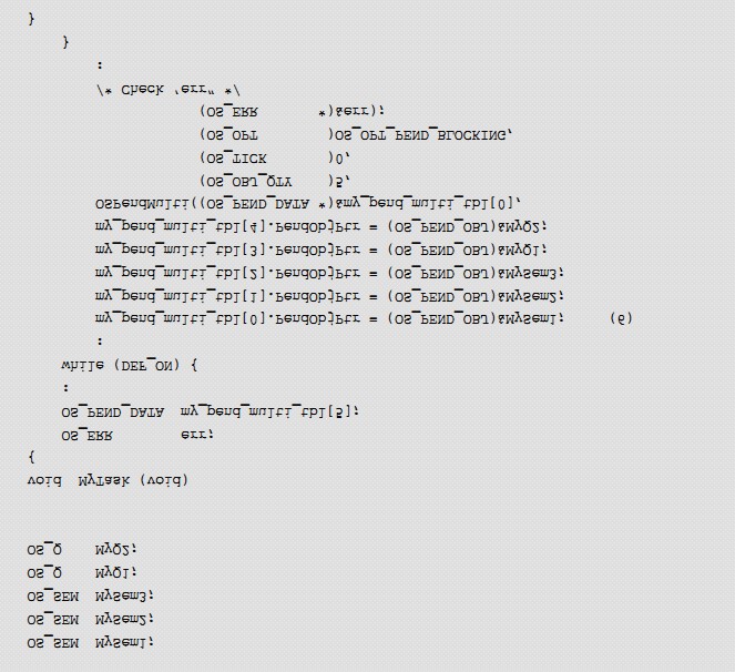
L16-1��2���ڶ�������Ϊ����Ĵ�С�����������Ϊ 5��
L16-1(2) This argument specifies the size of the
OS_PEND_DATA table. In the above example, this is 5.
L16-1��3�����õȴ����ޣ���������ʱ����û��һ�������ύ�ͻᳬʱ������ 0 ֵ��ʾ��Զ�ȴ���ȥ��
L16-1(3) Specify whether or not to timeout in case
none of the objects are posted within a certain amount of time. A non-zero
value indicates the number of ticks to timeout. Specifying zero indicates the
task will wait forever for any of the objects to be posted.
L16-1��4������"opt"�����˵ȴ��ķ�ʽ��OS_OPT_PEND_BLOCKING��OS_OPT_PEND_NON_BLOCKING���������𣩡�
L16-1(4) The ��opt�� argument specifies whether to wait
for objects to be posted (set opt to OS_OPT_PEND_BLOCKING) or, not block if
none of the objects have already been posted (set opt to
OS_OPT_PEND_NON_BLOCKING).
F16-2��1�������� uC/OS-III ����һ���������᷵�ش����˺���ִ�н���Ĵ�����š�
F16-2(1)
As with most ��C/OS-III function calls, specify the address of a variable that
will receive an error code based on the outcome of the function call. See
Appendix A, ����C/OS-III API Reference Manual�� on page 375 for a list of possible
error codes. As always, it is highly recommended to examine the error return
code.
F16-2��2�����еĶ�������Ͷ��� OS_PEND_OBJ��
F16-2(2) Note that all objects are cast to
OS_PEND_OBJ data types.
�� OSPendMulti()�����ã�������ȷ�����������е�Ԫ���Ƿ�ΪOS_SEM �� OS_Q��������ǣ��ͷ��ض�Ӧ�Ĵ�����š�
When
called, OSPendMulti() first starts by validating that all of the objects
specified in the OS_PEND_DATA table are either an OS_SEM or an OS_Q. If not, an
error code is returned.
OSPendMulti()�ȱ������飬�鿴���еĶ����Ƿ��Ѿ����ύ������У�OSPendMulti()���ڱ��и�������������Ӧ��ֵ��RdyObjPtr��RdyMsgPtr��.RdyMsgSize��.RdyTs��
Next,
OSPendMulti() goes through the OS_PEND_DATA table to see if any of the objects
have already posted. If so, OSPendMulti() fills the following fields in the
table: .RdyObjPtr, .RdyMsgPtr, .RdyMsgSize and .RdyTS.
.RdyObjPtr
ָ���Ѿ����ἰ�Ķ������磬�������� 0 ���ź����Ѿ����ύ����ô my_pend_multi_tbl[0].RdyObjPtr ��ֵ�ᱻ����Ϊ
my_pend_multi_tbl[0].PendObjPtr��
.RdyObjPtr
is a pointer to the object if
the object has been posted. For example, if the first object in the table is a
semaphore and the semaphore has been posted to, my_pend_multi_tbl[0].RdyObjPtr
is set to my_pend_multi_tbl[0].PendObjPtr.
.RdyMsgPtr
������и������ȴ�������Ϣ���У�������Ϣ�����գ���ô��ָ��ָ����Ϣ��
.RdyMsgPtr is a pointer to a message if the
object in the table at this entry is a message queue and a message was received
from the message queue.
.RdyMsgSize
������и������ȴ�������Ϣ���У�������Ϣ�����գ���ô��ֵΪ��Ϣ�����ݵĴ�С��
.RdyMsgSize is the size of the message received if the
object in the table at this entry is a message queue and a message was received
from the message queue.
.RdyTS ����Ŷ����ύʱ��ʱ�����
.RdyTS is the timestamp of
when the object posted. This allows the user to know when a semaphore or
message queue posts.
���û�ж����ύ��OSPendMulti()�ͻὫ����������ж���Ĺ�������У�����һ�����ӵIJ�����Ϊ��������Ҳ��������Щ�����еȴ���
If
there are no objects posted, then OSPendMulti() places the current task in the
wait list of all the objects that it is pending on. This is a complex and
tedious process for OSPendMulti() since there can be other tasks in the pend
list of some of these objects we are pending on.
ͼ 16-3 �������������ź����й�������ӣ�
To
indicate how tricky things get, Figure 16-3 is an example of a task pending on
two semaphores.
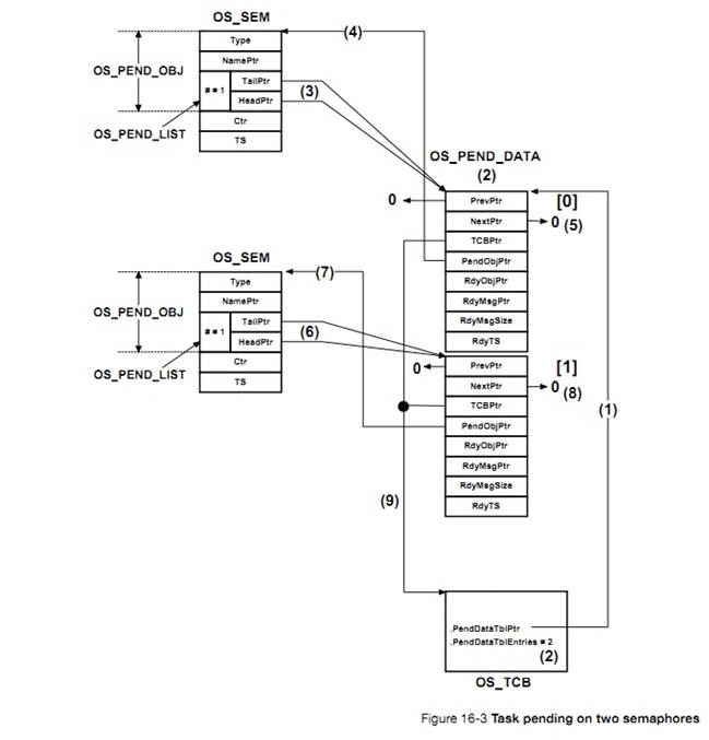
Figure
16-3 Task pending on two semaphores
F16-3��1������� OS_TCB ����ָ��ָ����
OS_PEND_DATA ��ɵı�����������������
F16-3(1)
A pointer to the base address of the OS_PEND_DATA table is placed in the OS_TCB
of the task placed in the pend list of the two semaphores.
F16-3��2��OS_TCB ����
OS_PEND_DATA ����ɵı��е� OS_PEND_DATA ��������������������¼��
F16-3(2)
The numbers of entries in the OS_PEND_DATA table are also placed in the OS_TCB.
Again, this task is waiting on two semaphores and therefore there are two
entries in the table.
F16-3��3����һ���ź���ָ���һ�� OS_PEND_DATA��
F16-3(3) Entry [0] of the OS_PEND_DATA table is
linked to the semaphore object specified by that entry��s .PendObjPtr.
F16-3��4��OS_PEND_DATA ���м�¼
0 ��.PendObjPtr ָ���һ���ź�����ͨ������
OSPendMulti()�ȴ������趨ָ��ָ��
F16-3(4) This pointer was specified by the caller
of OSPendMulti().
F16-3��5����Ϊ�ź�����ֻ�� 1 �������ڵȴ�������.PrevPtr ��.NextPtr ��ָ�� NULL��
F16-3(5) Since there is only one task in the pend
list of the semaphore, the .PrevPtr and .NextPtr are pointing to NULL.
F16-3��6���ڶ����ź���ָ��ڶ��� OS_PEND_DATA��
F16-3(6) The second semaphore points to the second
entry in the OS_PEND_DATA table.
F16-3��7��OS_PEND_DATA ���м�¼
0 ��.PendObjPtr ָ��ڶ����ź�����ͨ������
OSPendMulti()�ȴ������趨ָ��ָ��
F16-3(7) This pointer was specified by the caller
of OSPendMulti().
F16-3��8����Ϊ�ź�����ֻ�� 1 �������ڵȴ�������.PrevPtr ��.NextPtr ��ָ�� NULL��
F16-3(8) The second semaphore only has one entry
in its pend list. Therefore the .PrevPtr and .NextPtr both point to NULL.
F16-3��9����������ָ�����ӵ����� OS_PEND_DATA �ṹ�塣
F16-3(9) OSPendMulti() links back each
OS_PEND_DATA entry to the task that is waiting on the two semaphores.
ͼ 16-4 ��һ�����Ӹ��ӵ����ӣ�һ������ȴ������ź�������һ������ȴ����е�һ���ź���������ֻ�dz������ź�����Ҳ������չ����Ϣ���м����ߵ���ϡ�
Figure
16-4 is a more complex example where one task is pending on two semaphores
while another task also pends on one of the two semaphores. The examples
presented so far only show semaphores, but they could be combinations of
semaphores and message queues.
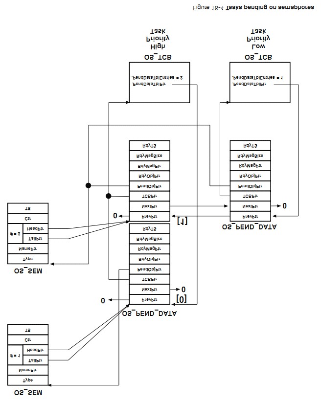
������� ISR ������Ϣ���ȴ�����Ϣ������OSPendMulti()���ء���ʾOS_PEND_DATA �����ж����ύ����Щͨ���ڱ�����Ӧ�����������Ӧֵʵ�֣���ͼ
16-2��
When
either an ISR or a task signals or sends a message to one of the objects that
the task is pending on, OSPendMulti() returns, indicating in the OS_PEND_DATA
table which object was posted. This is done by only filling in ��one�� of the
.RdyObjPtr entries, the one that corresponds to the object posted as shown in
Figure 16-2.
������ȴ� 5 ���ں˶���ʱ������������� OSPendMulti()֮ǰ�Ѿ���һ�������������ô���нṹ������ͼ 16-5
Only
one of the entries in the OS_PEND_DATA table will have a .RdyObjPtr with a
non-NULL value while all the other entries have the .RdyObjPtr set to NULL.
Going back to the case where a task waits on five semaphores and two message
queues, if the first message queue is posted while the task is pending on all
those objects, the OS_PEND_DATA table will be as shown in Figure 16-5.
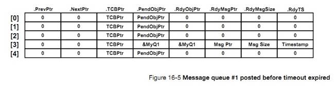
uC/OS-III
��������ȴ�����ں˶���
��C/OS-III
allows tasks to pend on multiple kernel objects.
OSPendMulti()ֻ�ܹ������ź�������Ϣ���С����ܹ������¼���־��� mutex��
OSPendMulti()
can only pend on multiple semaphores and message queues, not event flags and
mutual-exclusion semaphores.
�ڵ��� OSPendMulti()֮ǰ�����Ѿ����ύ��uC/OS-III�ᡰ���ߡ�OSPendMulti()��Щ�����Ѿ����ύ��
If
the objects are already posted when OSPendMulti() is called, ��C/OS-III will
specify which of the objects in the list of objects have already been posted.
���û�����ύ�Ķ���OSPendMulti()�ͻὫ����������ж���Ĺ�������С�����һ�������ύʱ
OSPendMulti()�ͻ᷵�ء�
If
none of the objects are posted, OSPendMulti() will place the calling task in
the pend list of all the desired objects.
����������£�OSPendMulti()�����ĸ������ѱ��ύ��
OSPendMulti()
will return as soon as one of the objects is posted. In this case,
OSPendMulti() will indicate which object was posted.
OSPendMulti()��һ�����ӵĺ��������ܻᵼ�³��ٽ�Ρ�
OSPendMulti()
is a complex function that has potentially long critical sections.
17���ڴ����
����ͨ��ʹ�ñ������ṩ�ĺ��� malloc()�� free()��̬�ط�����ͷ��ڴ�졣Ȼ������Ƕ��ʽʵʱϵͳ��ʹ�� malloc()�� free()�����Ƿdz�Σ�յġ���������ܻᵼ�ºܶ��ڴ���Ƭ��
An application
can allocate and free dynamic memory using any ANSI C compiler��s malloc() and
free() functions, respectively. However, using malloc() and free() in an
embedded real-time system may be dangerous. Eventually, it might not be
possible to obtain a single contiguous memory area due to fragmentation.
Fragmentation is the development of a large number of separate free areas
(i.e., the total free memory is fragmented into small, non-contiguous pieces).
Execution time of malloc() and free() is generally nondeterministic given the
algorithms used to locate a contiguous block of free memory.
uC/OS-III
���Ի���������ڴ�飬��ͼ 17-1 ��ʾ���ڴ���С������ͬ�����е��ڴ�����������������ڴ�顣���ض���ʱ��ִ���ڴ��ķ�����ͷš��ڴ�������ڴ���������ʽ����̬����ġ����������ͷţ�Ҳ���Ե��� malloc()��̬���䡣
��C/OS-III
provides an alternative to malloc() and free() by allowing an application to
obtain fixed-sized memory blocks from a partition made from a contiguous memory
area, as illustrated in Figure 17-1. All memory blocks are the same size, and
the partition contains an integral number of blocks. Allocation and
deallocation of these memory blocks is performed in constant time and is
deterministic. The partition itself is typically allocated statically (as an
array), but can also be allocated by using malloc() as long as it is never
freed.
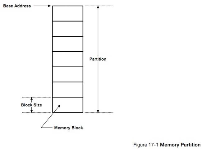
��ͼ 17-2 ��ʾ������ͬʱ�ж���ڴ������ÿ���������ڴ������ʹ�С���Բ�ͬ�������������ã����ڴ�鱻�������뷵�ظ������ڵ��ڴ���������ֹ�����ʽ���ᵼ���ڴ����ڵ���Ƭ��������Ӧ�����������ڴ��Ĵ�С��
As indicated
in Figure 17-2, more than one memory partition may exist in an application and
each one may have a different number of memory blocks and be a different size.
An application can obtain memory blocks of different sizes based upon
requirements. However, a specific memory block must always be returned to the
partition that it came from. This type of memory management is not subject to
fragmentation except that it is possible to run out of memory blocks. It is up
to the application to decide how many partitions to have and how large each
memory block should be within each partition.
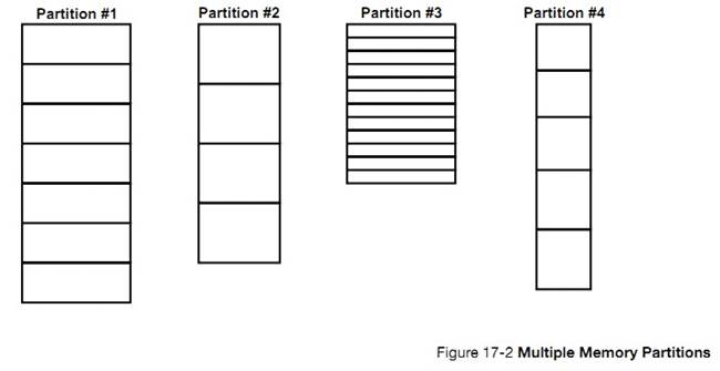
��ʹ���ڴ����֮ǰ���봴���������� uC/OS-III �Ϳ���֪������ڴ�����������Ϣ���������ǡ�����
OSMemCreate()����һ���ڴ��������ͼ 17-3 ��ʾ
Before
using a memory partition, it must be created. This allows ��C/OS-III to know
something about the memory partition so that it can manage their allocation and
deallocation. Once created, a memory partition is as shown in Figure 17-3.
Calling OSMemCreate() creates a memory partition.
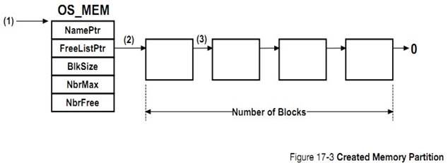
F13-3��1��������һ���ڴ����ʱ���ڴ���ƿ�(OS_MEM)�ĵ�ַ����Ϊ�������ṩ��ͨ���ڴ���ƿ�Ӿ�̬�ڴ��з��䣬Ȼ����Ҳ���Ե��� malloc()�Ӷ��л�á��û����벻���ͷ��ڴ���ƿ顣
F17-3(1) When creating a partition, the
application code supplies the address of a memory partition control block
(OS_MEM). Typically, this memory control block is allocated from static memory,
however it can also be obtained from the heap by calling malloc(). The
application code should however never deallocate it.
F13-3��2��OSMemCreate()���ڴ������������������������ַ��ֵ��OS_MEM �ṹ�塣
F17-3(2) OSMemCreate() organizes the continuous
memory provided into a singly linked list and stores the pointer to the
beginning of the list in the OS_MEM structure.
F13-3��3��ÿ���ڴ��Ĵ�С�������һ��ָ�롣
F17-3(3) Each memory block must be large enough to
hold a pointer. Given the nature of the linked list, a block needs to be able
to point to the next block.
�б� 17-1 ����ʾ������� uC/OS-III ����һ���ڴ����
Listing
17-1 indicates how to create a memory partition with ��C/OS-III.
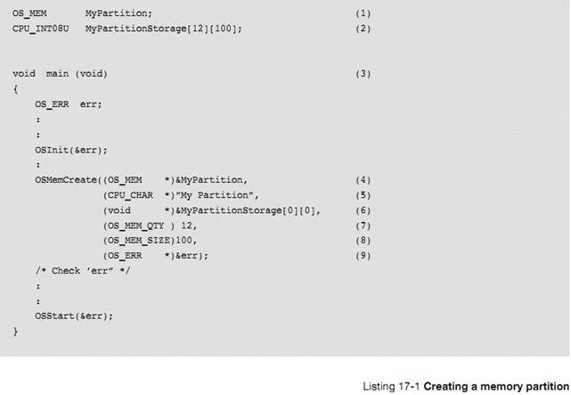
L17-1��1�����ڴ��������һ���ڴ���ƿ顣���Ծ�̬������� malloc() ���䡣���ǣ��û����벻��ɾ������ڴ���ƿ顣
L17-1(1)
An application needs to allocate storage for a memory partition control block.
This can be a static allocation as shown here or malloc() can be used in the
code.
However,
the application code must not deallocate the memory control block.
L17-1��2�����ڴ�����������ڴ�顣����Ծ�̬������� malloc() ���䡣
L17-1(2) The application also needs to allocate
storage for the memory that will be split into memory blocks. This can also be
a static allocation or malloc() can be used. The same reasoning applies. Do not
deallocate this storage since other tasks may rely on the existence of this
storage.
L17-1��3���ڴ�����ڱ�����֮ǰ�豻�����ڴ���ƿ���ڴ�顣����� main()�д����ڴ��������Ȼ��Ҳ������ main()�е����ܷ����ڴ�����ĺ�����
L17-1(3) Memory partition must be created before
allocating and deallocating blocks from the partition. One of the best places
to create memory partitions is in main() prior to starting the multitasking
process. Of course, an application can call a function from main() to do this
instead of actually placing the code directly in main().
L17-1��4�����ڴ���ƿ�ĵ�ַ���ݸ� OSMemCreate()���û����벻�ܷ��� OS_MEM �ṹ�塣ֻ��ͨ�� uC/OS-III �� API ���ʡ�
L17-1(4) Pass the address of the memory partition
control block to OSMemCreate(). Never reference any of the internal members of
the OS_MEM data structure.
Instead,
use ��C/OS-III��s API.
L17-1��5�����ڴ��������һ�����֡�
L17-1(5) Assign a name to the memory partition.
There is no limit to the length of the ASCII string as ��C/OS-III saves a
pointer to the ASCII string in the partition control block and not the actual
characters.
L17-1��6�����ڴ���������ַ���ݸ� OSMemCreate()��
L17-1(6) Pass the base address of the storage area
reserved for the memory blocks.
L17-1��7���ò���Ϊ������ڴ�������ڴ������
L17-1(7) Specify how many memory blocks are
available from this memory partition. Hard coded numbers are used for the sake
of the illustration but one should instead use #define constants.
L17-1��8���������ڴ������ÿ���ڴ��Ĵ�С��������ֵ��Ϊ��˵���������#define ����ĺ���档
L17-1(8) Specify the size of each memory block in
the partition. Again, a hard coded value is used for illustration, which is not
recommended in real code.
L17-1��9��OSMemCreate()���ݺ�����ִ�н������һ��������š�
L17-1(9) As with most ��C/OS-III services,
OSMemCreate() returns an error code indicating the outcome of the service. The
call is successful if ��err�� contains
OS_ERR_NONE.
�б� 17-2 ���������ʹ�� malloc()����һ���ڴ������ͬ���ģ��û����벻���ͷ��ڴ���ƿ���ڴ�顣
Listing
17-2 shows how to create a memory partition with ��C/OS-III, this time using
malloc() to allocate storage. Do not deallocate the memory control block or the
storage for the partition.
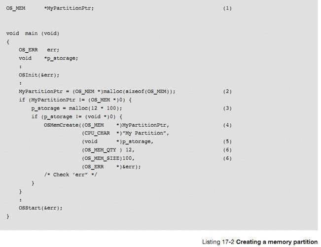
L17-2��1������һ��ָ��ָ�� malloc()������ڴ���ƿ顣
L17-2(1) Instead of allocating static storage for
the memory partition control block, assign a pointer that receives the OS_MEM
allocated using malloc().
L17-2��2��malloc()����ռ���ڴ���ƿ�
OS_MEM��
L17-2(2) The application allocates storage for the
memory control block.
L17-2��3�����ڴ���������ڴ�顣
L17-2(3) Allocate storage for the memory
partition.
L17-2��4���� OS_MEM �ĵ�ַ���ݸ�
OSMemCreate()��
L17-2(4) Pass a pointer to the allocated memory
control block to OSMemCreate().
L17-2��5�����ڴ��Ļ���ַ���ݸ� OSMemCreate()��
L17-2(5) Pass the base address of the storage used
for the partition.
L17-2��6��������ڴ��ĸ����ʹ�С�� OSMemCreate()��ͬ���ģ������ַ�����Ϊ��˵�����������#defines ����ĺ곣�����档
L17-2(6) Finally, pass the number of blocks and
the size of each block so that ��C/OS-III creates the linked list of 12 blocks
of 100 bytes each. Again, hard coded numbers are used, but these would
typically be replaced by #defines.
Ӧ�ô���ͨ������ OSMemGet()���Դ��ڴ�����������ڴ�顣���б� 17-3 ��ʾ�����ٶ��ڴ�����Ѿ���������
Application
code can request a memory block from a partition by calling OSMemGet() as shown
in Listing 17-3. The code assumes that the partition was already created.
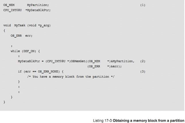
L17-3��1������Ҫ���ʸ��ڴ����������� ISR ������Է�������ڴ�������ڴ���ƿ顣���ڴ���ƿ�������� ISR ��������Χ�ڣ�
L17-3(1) The memory partition control block must
be accessible by all tasks or ISRs that will be using the partition.
L17-3��2������ OSMemGet()���ڴ�����л��һ���ڴ�顣�������غ��ָ�뽫ָ�����ڴ��Ļ���ַ���������� malloc()��
L17-3(2) Simply call OSMemGet() to obtain a memory
block from the desired partition. A pointer to the allocated memory block is
returned. This is similar to malloc(), except that the memory block comes from
a pool that is guaranteed to not fragment.
L17-3��3�����ݷ��صĴ�����ż�⺯����ִ�н����
L17-3(3) It is important to examine the returned
error code to ensure that there are free memory blocks and that the application
can start putting content in the memory blocks.
���û����ڴ���ʹ����Ϻ��뽫���ڴ��黹����Ӧ���ڴ���������� OSMemPut()ʵ��������ܡ����б� 17-4 ��ʾ��
The
application code must return an allocated memory block back to the proper
partition when finished. Do this by calling OSMemPut() as shown in Listing
17-4. The code assumes that the partition was already created.
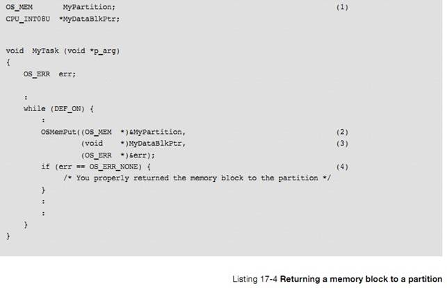
L17-4��1������Ҫ���ʸ��ڴ����������� ISR ������Է�������ڴ�������ڴ���ƿ顣
L17-4(1) The memory partition control block must be
accessible by all tasks or ISRs that will be using the partition.
L17-4��2������ OSMemPut()���ڴ��黹����Ӧ�ڴ������ע����� uC/OS-III ������ڴ���Ƿ黹����Ӧ�ڴ����������ʹ��ʱ����dz�С�ġ�
L17-4(2) Simply call OSMemPut() to return the
memory block back to the memory partition. Note that there is no check to see
whether the proper memory block is being returned to the proper partition
(assuming you have multiple different partitions). It is therefore important to
be careful (as is necessary when designing embedded systems).
L17-4��3����ָ��ָ��Ҫ�黹���ڴ���ַ����������Ϊ"void *"��
L17-4(3) Pass the pointer to the data area that is
allocated so that it can be returned to the pool. Note that a ��void *�� is
assumed.
L17-4��4����������š�
L17-4(4) Examine the returned error code to ensure
that the call was successful.
����ʱ���� OS_CFG.H �е� OS_CFG_MEM_EN Ϊ 1 �����ڴ��������
Memory
management services are enabled at compile time by setting the configuration
constant OS_CFG_MEM_EN to 1 in OS_CFG.H.
�� 13-1 ���ڴ������غ������ܽᡣ
There
are a number of operations to perform on memory partitions as summarized in
Table 13-1.
|
������
|
����
|
|
OSMemCreate()
|
����һ���ڴ����
Create a memory partition.
|
|
OSMemGet()
|
���ڴ�����л��һ���ڴ��
Obtain a memory block from a memory partition.
|
|
OSMemPut()
|
�黹һ���ڴ�����Ӧ���ڴ����
Return a memory block to a memory partition.
|
�� 17-1 �ڴ���� API �ܽ�
OSMemCreate()ֻ�����������ã����� OSMemGet()��OSMemPut()������ ISR �б����á�
OSMemCreate()
can only be called from task-level code, but OSMemGet() and OSMemPut() can be
called by Interrupt Service Routines (ISRs).
�б� 17-4 ��ʾ����ζ�̬�ط����ڴ档����������У���������ȡģ������ֵ��������ѹ�����¶ȡ���ѹ������������Ϣ���ұ�������Ϣ�а����˸���ģ��������������������Ϣ�ĵ�ַ��
Listing
17-4 shows an example of how to use the dynamic memory allocation feature of
��C/OS-III, as well as message-passing capabilities (see Chapter 15, ��Message
Passing�� on page 289). In this example, the task on the left reads and checks
the value of analog inputs (pressures, temperatures, and voltage) and sends a
message to the second task if any of the analog inputs exceed a threshold. The
message sent contains information about which channel had the error, an error
code, an indication of the severity of the error, and other information.
����������д���Ĵ������������ұ������С���������� ISRҲ���Է�����Ϣ���ô���������
Error
handling in this example is centralized. Other tasks, or even ISRs, can post
error messages to the error-handling task. The error-handling task could be
responsible for displaying error messages on a monitor (a display), logging
errors to a disk, or dispatching other tasks to take corrective action based on
the error.
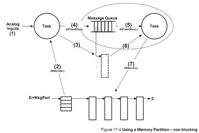
F17-4��1�������ȡģ�����롣������ģ�����볬��Χ���ͷ�����Ϣ��������������
F17-4(1) The analog inputs are read by the task.
The task determines that one of the inputs is outside a valid range and an
error message needs to be sent to the error handler.
F17-4��2��������ڴ����������һ���ڴ�����ڴ�ż��ģ���������õ�������ݡ�
F17-4(2) The task then obtains a memory block from
a memory partition so that it can place information regarding the detected
error.
F17-4��3�������ģ���������õ�������ݴ����ڴ�顣Ȼ����û��Ҫ���ڴ���д��ʱ�����Ϊʱ������������Ϣ�С�
F17-4(3) The task writes this information to the
memory block. As mentioned above, the task places the analog channel that is at
fault, an error code, an indication of the severity, possible solutions, and
more. There is no need to store a timestamp in the message, as time stamping is
a built-in feature of ��C/OS-III so the receiving task will know when the
message was posted.
F17-4��4�������ύ��Ϣ������������Ȼ������������֪����Ϣ�������������ݵĺ��塣һ����Ϣ�����ͣ��������������ٷ�����Ϣ��ָ����ڴ�顣
F17-4(4) Once the message is complete, it is
posted to the task that will handle such error messages. Of course the
receiving task needs to know how the information is placed in the message. Once
the message is sent, the analog input task is no longer allowed (by convention)
to access the memory block since it sent it out to be processed.
F17-4��5������������ͨ������Ϣ�����еȴ���
F17-4(5) The error handler task (on the right)
normally pends on the message queue.
This
task will not execute until a message is sent to it.
F17-4��6��������������յ���Ϣ��ִ����Ӧ�IJ�����
F17-4(6) When a message is received, the error
handler task reads the contents of the message and performs necessary
action(s). As indicated, once sent, the sender will not do anything else with
the message.
F17-4��7�������������������Ӧ�IJ������ڴ��黹����Ӧ���ڴ��������ˣ������ߺͽ����߶�����֪���ڴ���������ĸ��ڴ�����ģ����߷����߿��Խ��ڴ�����ĵ�ַ��ΪҪ������Ϣ�������е�һ���֡�������������������֪��������ڴ��黹���ĸ��ڴ�����ˡ�
F17-4(7) Once the error handler task is finished
processing the message, it simply returns the memory block to the memory
partition. The sender and receiver therefore need to know about the memory
partition or, the sender can pass the address of the memory partition as part
of the message and the error handler task will know where to return the memory
block.
�������ڴ������������ʱ���Եȴ��ڴ�顣uC/OS-III ��֧������ȴ��ڴ���������ǿ���ͨ��һ���ź��������ڴ�������ڴ��ķ��䡣��ͼ 17-5
Sometimes
it is useful to have a task wait for a memory block in case a partition runs
out of blocks. ��C/OS-III does not support pending on partitions, but it is
possible to support this requirement by adding a counting semaphore (see
Chapter 13, ��Resource Management�� on page 209) to guard the memory partition.
This is illustrated in Figure 17-5.
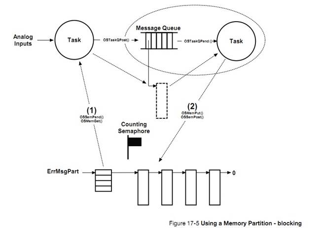
F17-5��1�����һ���ڴ��ʱ���ȵ��� OSSemPend()���һ���ź�����Ȼ���ٵ��� OSMemGet()���һ���ڴ�顣
F17-5(1)
To obtain a memory block, simply obtain the semaphore by calling OSSemPend() and
call OSMemGet() to receive the memory block.
F17-5��2���ͷ�һ���ڴ��ʱ���ȵ��� OSMemPut()�ͷ�����ڴ�飬Ȼ���ٵ��� OSSemPost()�ͷ�����ź�����
F17-5(2)
To release a block, simply return the memory block by calling OSMemPut() and
signal the semaphore by calling OSSemPost().
����IJ������������˳��ִ�С�
The
above operations must be performed in order.
�û������� ISR ��ʹ�� OSMemGet()��
OSMemPut()����Ϊ�������������ᱻ�������ܿ��ٵر�ִ�С��������� ISR �е��û����������ĺ�����
Note
that the user may call OSMemGet() and OSMemPut() from an ISR since these
functions do not block and in fact, execute very quickly. However, you cannot
use blocking calls from ISRs.
��Ҫ��Ƕ��ʽϵͳ��ʹ�� malloc()�� free()����Ϊ�����ᵼ���ڴ���Ƭ��
{����˵���岻��Ҫ�ͷŵĿռ�ʱ����ʹ�� malloc()��������ʹ������Ŀռ�������ʽӽ�Ϊ 100%}
Do
not use malloc() and free() in embedded systems since they lead to
fragmentation.
������ malloc()��̬�ķ����ڴ�ռ䣬����Ҫ�ͷ���Щ�ڴ�ռ䡣
It
is possible to use malloc() to allocate memory from the heap, but do not
deallocate the memory.
�û����Դ���������ڴ�����������ڴ������� RAM����
The
application programmer can create an unlimited number of memory partitions
(limited only by the amount of available RAM).
Memory
partition services in ��C/OS-III start with the OSMem???() prefix, and the
services available to the application programmer are described in Appendix A,
����C/OS-III API Reference Manual�� on page 375.
uC/OS-III
�����ڴ������صĺ��������� OSMem???()Ϊǰ�������¼ A��
ͨ������ OS_CFG.H �е� OS_CFG_MEM_EN Ϊ 1 �����ڴ��������
Memory
management services are enabled at compile time by setting the configuration
constant OS_CFG_MEM_EN to 1 in OS_CFG.H.
OSMemGet()�� OSMemPur()������ ISR �б����á�
OSMemGet()
and OSMemPut() can be called from ISRs.
18����ֲ uC/OS-III
����½ڽ����������ֲ uC/OS-III ����ͬ�Ĵ������С�Ϊ����߿���ֲ�ԣ���������� uC/OS-III
���붼���� C ��д�ġ�Ȼ����������һЩ������ض��Ĵ���������д��Ӧ�� C �ͻ����롣����uC/OS-III ֱ�ӿ��ƴ������Ĵ������ֵĴ��룬��ֻ���û��ʵ�֡�
This
chapter describes in general terms how to adapt ��C/OS-III to different
processors. Adapting ��C/OS-III to a microprocessor or a microcontroller is
called porting. Most of ��C/OS-III is written in C for portability. However, it
is still necessary to write processor-specific code in C and assembly language.
��C/OS-III manipulates processor registers, which can only be done using
assembly language.
��Ϊ uC/OS-III ������
uC/OS-II���û������ȴ���ֲ uC/OS-II ��ʼ��
Porting
��C/OS-III to different processors is relatively easy as ��C/OS-III was designed
to be portable and, since ��C/OS-III is similar to ��C/OS-II, the user can start
from a ��C/OS-II port. If there is already a port for the processor to be used,
it is not necessary to read this chapter unless, of course, there is an
interest in knowing how ��C/OS-III processor-specific code works.
�����������������������������ֲ uC/OS-III��
��C/OS-III
can run on a processor if it satisfies the following general requirements:
�� �������ж�Ӧ���ܲ������������� C ������
The
processor has an ANSI C compiler that generates reentrant code.
�� ������֧���ж������ṩ�����Ե��жϣ�ͨ������ 10 �� 1000Hz ֮�䣩��
The
processor supports interrupts and can provide an interrupt that occurs at
regular intervals (typically between 10 and 1000 Hz).
�� ���Թ��жϺͿ��ж�
Interrupts
can be disabled and enabled.
�� ������֧�ִ洢�������ջָ�롢CPU �Ĵ�������ջ��ָ�
The
processor supports a hardware stack that accommodates a fair amount of data
(possibly many kilobytes).
��
The
processor has instructions to save and restore the stack pointer and other CPU
registers, either on the stack or in memory.
�� ���������㹻�� RAM ���ڴ�� uC/OS-III �ı������ṹ�塢�ڲ������ջ�������ջ��
The
processor has access to sufficient RAM for ��C/OS-III��s variables and data
structures as well as internal task stacks.
�� ������֧�� 64 λ����������
The
compiler should support 64-bit data types (typically ��long long��).
ͼ 18-1 ��ʾ�� uC/OS-III �ļܹ�����������������Ӳ���ɷֵĹ�ϵ��
Figure
18-1 shows the ��C/OS-III architecture and its relationship with other software
components and hardware. When using ��C/OS-III in an application, the user is
responsible for providing application software and ��C/OS-III configuration
sections.
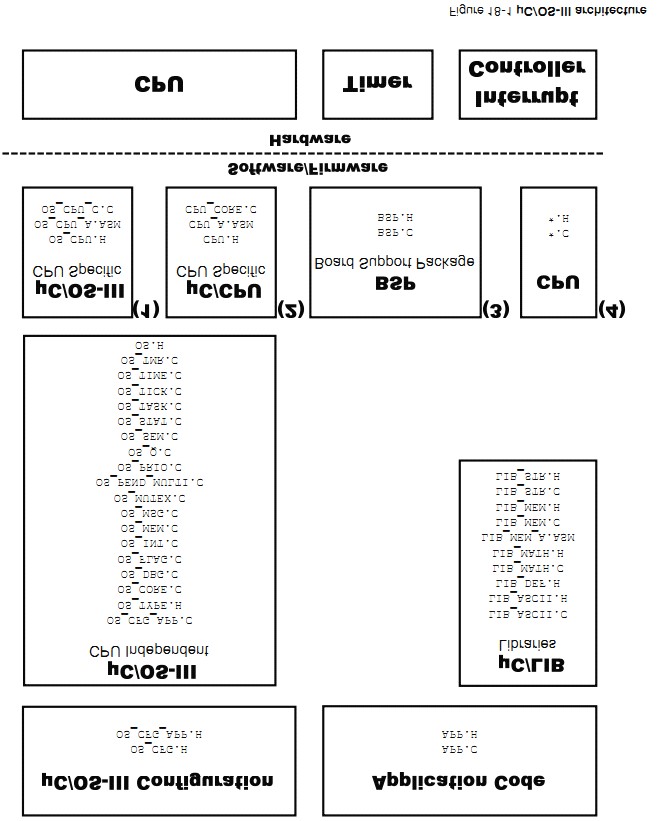
F18-1��1����ֲ uC/OS-III ���� 3
�����ں���ص��ļ���OS_CPU.H��
OS_CPU_A.ASM��OS_CPU_C.C��
F18-1(1) A ��C/OS-III port consists of writing or
changing the contents of three kernel-specific files: OS_CPU.H, OS_CPU_A.ASM
and OS_CPU_C.C.
F18-1��2����ֲ uC/OS-III ���� 3
���� CPU ��ص��ļ���CPU.H��
CPU_A.ASM��CPU_CORE.C��
F18-1(2) A port also involves writing or changing
the contents of three CPU specific files: CPU.H, CPU_A.ASM and CPU_CORE.C.
F18-1��3��BSP ��ͨ��������
uC/OS-III �붨ʱ��������ʱ���Ķ�ʱ�������жϿ������Ľӿڡ�
F18-1(3) A Board Support Package (BSP) is
generally necessary to interface ��C/OS-III to a timer (which is used for the
clock tick) and an interrupt controller.
F18-1��4����Щ�뵼�峧�̻������Ӧ�Ĺ̼����ļ�����Щ�ļ��ᱻ������ CPU/MCU �С�
F18-1(4) Some semiconductor manufacturers provide
source and header files to access on-chip peripherals. These are contained in
CPU/MCU specific files.
���ݲ�ͬ�Ĵ���������ֲ���ܻ�ı� 100 �� 400 �д��롣
Porting
��C/OS-III is quite straightforward once the subtleties of the target processor
and the C compiler/assembler are understood. Depending on the processor, a port
consists of writing or changing between 100 and 400 lines of code, which takes
a few hours to a few days to accomplish. The easiest thing to do, however, is
to modify an existing port from a processor that is similar to the one intended
for use.
uC/OS-III
����ֲ�������� uC/OS-II ����ֲ���� uC/OS-II
ת���� uC/OS-III ��Լ��ҪһСʱʱ�䡣������������¼ C��
A
��C/OS-III port looks very much like a ��C/OS-II port. Since ��C/OS-II was ported
to well over 45 different CPU architectures it is easy to start from a ��C/OS-II
port. Converting a ��C/OS-II port to ��C/OS-III takes approximately an hour. The
process is described in Appendix C, ��Migrating from ��C/OS-II to ��C/OS-III�� on
page 599.
��ֲ�������������ݣ�CPU��OS��BSP��
A
port involves three aspects: CPU, OS and board-specific code. The
board-specific code is often called a Board Support Package (BSP) and from ��C/OS-III��s
point of view, requires very little.
�� CPU ��صĴ�������� CPU �ļܹ������磬���жϺͿ��жϡ���ջ���ֳ�����ջ����������ȵȡ��� CPU ��صĴ��뱻��װ�ڽ��� uC/CPU ��ģ���С�
CPU-specific
code is related to the CPU and the compiler in use, and less so with ��C/OS-III.
For example, disabling and enabling interrupts and the word width of the stack,
whether the stack grows from high-to-low memory or from low-to-high memory and
more are all CPU specific and not OS specific. Micri��m encapsulates CPU
functions and data types into a module called ��C/CPU.
�� 18-1 ����ʾ�� uC/CPU �е��ļ����������ڵ�λ�á�
Table
18-1 shows the name of ��C/CPU files and where they should be placed on the
computer used to develop a ��C/OS-III-based application.
Here,
<processor> is the name of the processor that the CPU*.* files apply to,
and <compiler> is the name of the compiler that these files assume
because of different assembly language directives that different tool chains
use.
The
above source files for the CPU that came with this book are found when
downloading the code from the Micri��m website.
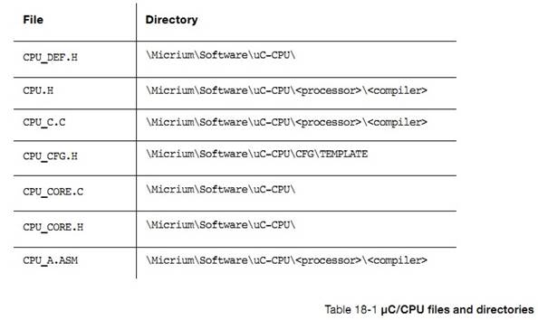
CPU_DEF.H
���ļ�����Ҫ���ı䣺CPU_DEF.H �а����� Micrium ��˾�ṩ���������õ���#define ����ĺꡣ
This
file should not require any changes. CPU_DEF.H declares #define constants that
are used by Micri��m software components.
CPU.H
��ͬ CPU ����ֳ����ܲ�ͬ��CPU.H �ж����˺ܶ��������͡��� Micrium ��˾�У�����ʹ�� C ���������������� int��short��long��char �ȣ����Ƕ����˸����ڿ������������͡����ı��������û��ֲᣬ����������������Ӧ���ֳ������ʹ�� 32 λ CPU ʱ�����µĶ�������ı䡣
Many
CPUs have different word lengths and CPU.H declares a series of type
definitions that ensure portability. Specifically, at Micri��m, C data types
int, short, long, char, etc., are not used. Instead, clearer data types are
defined. Consult compiler documentation to determine whether the standard
declarations described below must be changed for the CPU/compiler used. When
using a 32-bit CPU, the declarations below should work without change.
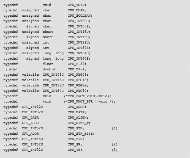
(1)uC/OS-III
�зdz���Ҫ������������ CPU_STK���������˶�ջ�ij��ȡ�������ѹ��͵�����ջ�������� 8 λ��16 λ��32 λ������64 λ�ġ�
Especially
important for ��C/OS-III is the definition of the CPU_STK data type, which sets
the width of a stack entry. Specifically, is the width of data pushed to and
popped from the stack 8 bits, 16 bits, 32 bits or 64 bits?
(2)
CPU_SR �������ͱ�ʾ���Ǵ�������״̬�Ĵ������ж�ʱ���ڱ��� CPU ״̬�ļĴ�����
CPU_SR
defines the data type for the processor��s status register (SR) that generally
holds the interrupt disable status.
(3)
CPU_TS ��ʱ������������͡�
The
CPU_TS is a time stamp used to determine when an operation occurred, or to
measure the execution time of code.
CPU.H
��Ҳ�����˹��жϡ����жϵĺ꣺CPU_CRITICAL_ENTER()��CPU_CRITICAL_EXIT()�����ж����� CPU_C.C �� CPU_CORE.C �к�����ԭ�͡�
CPU.H
also declares macros to disable and enable interrupts: CPU_CRITICAL_ENTER() and
CPU_CRITICAL_EXIT(), respectively. Finally, CPU.H declares function prototypes
for a number of functions found in either CPU_C.C or CPU_CORE.C.
CPU_C.C
���Ǹ���ѡ���ļ�������� CPU ���жϿ���������ʱ������ش��롣�������Ӧ�����Dz���������ļ��ġ�
This
is an optional file containing CPU-specific functions to set the interrupt
controller, timer prescalers, and more. Most implementations will not contain
this file.
CPU_CFG.H
���Ǹ������ļ�������Ӧ�ø�����Ӧ��#define��
This
is a configuration file to be copied into the product directory and changed
based on the options to exercise in ��C/CPU. The file contains #define constants
that may need to be changed based on the desired use of ��C/CPU. For example, to
assign a ��name�� to the CPU, the name can be queried and displayed. Also, to
name the CPU, one must specify the length of the ASCII string.
CPU_CORE.C
����ͨ�õ��ļ�������Ҫ���ı䡣Ȼ���������뱻������
This
file is generic and does not need to be changed. However it must be included in
all builds.
CPU_CORE.C
�ж����� CPU_Init()��CPU_CntLeadZeros()�Լ�����CPU �����ж�ʱ��ĺ����ȡ�
CPU_CORE.C
defines such functions as CPU_Init(), CPU_CntLeadZeros(), and code to measure
maximum CPU interrupt disable time.
�����ڵ��� OSInit()֮ǰ���� CPU_Init()��
CPU_Init()
must be called before calling OSInit().
CPU_CntLeadZeros()�����������ڲ���������ȼ��ľ������� CPU_CORE.C �� C ģ���˼�������ָ�������������и�ָ���ô��#define CPU_CFG_LEAD_ZEROS_ASM_PRESENT��CPU_CntLeadZeros()�����û�����Ա�д�ĺ������棨����CPU_A.ASM �У���ʹ���������֮ǰ���� CPU.H �ж���CPU_CFG_DATA_SIZE ��ֵ��
CPU_CntLeadZeros()
is used by the ��C/OS-III scheduler to find the highest priority ready task (see
Chapter 7, ��Scheduling�� on page 133). CPU_CORE.C implements a count leading
zeros in C. However, if the processor used provides a built-in instruction to
count leading zeros, define CPU_CFG_LEAD_ZEROS_ASM_PRESENT, and replace this
function by an assembly language equivalent (in CPU_A.ASM). It is important to
properly declare CPU_CFG_DATA_SIZE in CPU.H for this function to work.
CPU_CORE.C
��Ҳ�������ܶ�ȡʱ����ĺ�����uC/CPU ��ʱ����� 32 λ�ġ�Ȼ����uC/CPU ���Է��� 64 λ��ʱ�������ʱ�������֪���¼�������ʱ�̣����Բ��������ִ��ʱ�䡣ʹ��ʱ�����ǰ���� CPU ����ֵ���Ա���ȡ����ȡʱ����Ĵ�����Ա����� BSP �С�
CPU_CORE.C
also includes code that allows you to read timestamps. ��C/CPU timestamps
(CPU_TS) are 32-bit values. However, ��C/CPU can return a 64-bit timestamp since
��C/CPU keeps track of overflows of the low part of the 64-bit timestamp. Also
use timestamps to determine when events occur, or to measure the execution time
of code. Timestamp support requires a 16- or 32-bit free-running counter/timer
that can be read. The code to read this timer will be placed in the BSP (Board
Support Package) of the evaluation board or target board used.
CPU_CORE.H
��������� CPU_CORE.C �к�����ԭ�͡�
This
header file is required by CPU_CORE.C to define function prototypes.
CPU_A.ASM
����ļ��а����˻����룬����жϺ��������жϺ������������㺯���ȴ�����ͳ̶ȣ������������� CPU_SR_Save()��CPU_SR_Restore()��
This
file contains assembly language code to implement such functions as disabling
and enabling interrupts, a more efficient count leading zeros function, and
more. At a minimum, this file should implement CPU_SR_Save() and
CPU_SR_Restore().
CPU_SR_Save()���ж�ʱ���浱ǰ CPU ��״̬�Ĵ�������ջ��Ȼ�����ڷ���ʱ������ص��жϡ�CPU_SR_Save()����CPU_CRITICAL_ENTER()���á�
CPU_SR_Save()
reads the current value of the CPU status register where the current interrupt
disable flag resides and returns this value to the caller. However, before
returning, CPU_SR_Save() must disable all interrupts. CPU_SR_Save() is actually
called by the macro CPU_CRITICAL_ENTER().
CPU_SR_Restore�����ָ��ж�ǰ CPU ��״̬�Ĵ�����CPU_SR_Restore()���� CPU_CRITICAL_EXIT()���á�
CPU_SR_Restore()
restores the CPU��s status register to a previously saved value.
CPU_SR_Restore() is called from the macro CPU_CRITICAL_EXIT().
�� 18-2 ��ʾ���豻���õ� uC/OS-III �ļ���
Table
18-2 shows the name of ��C/OS-III files and where they are typically found.
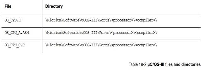
Here,
<processor> is the name of the processor that the OS_CPU*.* files apply
to, and <compiler> is the name of the compiler that these files assume
because of the different assembly language directives that different tool
chains use.
OS_CPU.H
����ļ��б��붨��� OS_TASK_SW()������걻
OSSched()�����������������
This
file must define the macro OS_TASK_SW(), which is called by OSSched() to
perform a task-level context switch. The macro can translate directly to a call
to OSCtxSw(), trigger a software interrupt, or a TRAP. The choice depends on
the CPU architecture.
OS_CPU.H
OS_CPU.H
�б��붨��� OS_TS_GET()�����ڻ�õ�ǰ��ʱ�����ʱ�������������Ϊ CPU_TS���� 32 λ�ġ�
OS_CPU.H
must also define the macro OS_TS_GET() which obtains the current time stamp. It
is expected that the time stamp is type CPU_TS, which is typically declared as
at least a 32-bit value.
OS_CPU.H
�л���Ҫ���� OSCtxSw()��OSIntCtxSw()�� OSStartHighRdy()�Ⱥ�����ԭ�͡�
OS_CPU.H
also defines function
prototypes for OSCtxSw(), OSIntCtxSw(),OSStartHighRdy()
and possibly other functions required by the port.
OS_CPU_A.ASM
����ļ��а��������»�ຯ����
This
file contains the implementation of the following assembly language functions:
OSStartHighRdy()
OSCtxSw()
OSIntCtxSw()
��һ����ѡ����
and
optionally,
OSTickISR()
OS_CPU_A.ASM
�д�ŵĴ����ֱ�Ӳ��� CPU �Ĵ����ĺ�������Щ�������ܱ�
C ����ʵ�֡�
OSTickISR()
may optionally be placed in OS_CPU_A.ASM if it does not change from one product
to another. The functions in this file are implemented in assembly language
since they manipulate CPU registers, which is typically not possible from C.
The functions are described in Appendix A, ����C/OS-III API Reference Manual�� on
page 375.
OS_CPU_C.C
����ļ��а����˹��Ӻ�����
This
file contains the implementation of the following C functions:
OSIdleTaskHook()
OSInitHook()
OSStatTaskHook()
OSTaskCreateHook()
OSTaskDelHook()
OSTaskReturnHook()
OSTaskStkInit()
OSTaskSwHook()
OSTimeTickHook()
�����¼ A��OS_CPU_C.C �п��Զ�����������������Щ������ǿ�Ƶġ�
The
functions are described in Appendix A, ����C/OS-III API Reference Manual�� on page
375. OS_CPU_C.C can declare other functions as needed by the port, however the
above functions are mandatory.
�弶֧�ְ��Ĵ�����û���ʹ�õ�Ŀ����йء����磬BSP �ж���ĺ������ڿ����ر� LED��������ֵ����ʼ��ʱ�ӵȡ�
A
board support package refers to code associated with the actual evaluation board
or the target board used. For example, the BSP defines functions to turn LEDs
on or off, reads push-button switches, initializes peripheral clocks, etc.,
providing nearly any functionality to multiple products/projects.
BSP
���ļ�������
Names
of typical BSP files include:
BSP.C
BSP.H
BSP_INT.C
BSP_INT.H
��Щ�ļ����ڵ�Ŀ¼Ϊ��
All
files are generally placed in a directory as follows:
Here,
<manufacturer> is the name of the evaluation board or target board
manufacturer, <board_name> is the name of the evaluation or target board
and <compiler> is the name of the compiler that these files assume,
although most should be portable to different compilers since the BSP is
typically written in C.
BSP.C �� BSP.H
�������ļ��а����˺����Ķ���������� BSP_Init()��BSP_LED_On()��BSP_LED_Off()��BSP_LED_Toggle()��BSP_PB_Rb() �ȡ��û����Զ����Լ��ĺ���������� BSP_��Ϊǰ��
These
files normally contain functions and their definitions such as BSP_Init(),
BSP_LED_On(), BSP_LED_Off(), BSP_LED_Toggle(), BSP_PB_Rd(), and others. It is
up to the user to decide if the functions in this file start with the prefix
BSP_. In other words, use LED_On() and PB_Rd() if this is clearer. However, it
is a good practice to encapsulate this type of functionality in a BSP type file.
�� BSP.C �У��������� CPU_TS_TmrInit()���ڳ�ʼ�� CPU ��ʱ�����ʡ�
In
BSP.C, add CPU_TS_TmrInit() to initialize the ��C/CPU timestamp feature. This
function must return the number 16 if using a 16-bit timer and 0 for a 32-bit
timer.
CPU_TS_TmrGet()���ڶ�ȡ CPU ʱ�Ӽ���ֵ�������ʱ���� 16 λ�ģ���ô���趨�������֣�����ת��Ϊ 32 λ�ġ������ʱ���� 32 λ�ģ�CPU_TS_TmrGet()��ֱ�ӷ������ 32 λ��ֵ��
CPU_TS_TmrGet()
is responsible for reading the value of a 16- or 32-bit free-running timer. If
the timer is 16 bits, this function will need to return the value of the timer,
but shifted to the left 16 places so that it looks like a 32-bit timer. If the
timer is 32 bits, simply return the current value of the timer. Note that the
timer is assumed to be an up counter. If the timer counts down, the BSP code
will need to return the ones-complement of the timer value
(prior
to the shift).
BSP_INT.C �� BSP_INT.H
��Щ�ļ������ڴ�����жϿ�������صĺ��������磬���������ض��Ĺ��жϡ����жϣ���Ӧ�жϿ��������������жϵ� ISR ָ��ͬһ��ַ�ȣ� ���� 9 �¡��жϹ���������
These
files are typically used to declare interrupt controller related functions. For
example, code that enables or disables specific interrupts from the interrupt
controller, acknowledges the interrupt controller, and code to handle all
interrupts if the CPU vectors to a single location when an interrupt occurs
(see Chapter 9, ��Interrupt Management�� on page 157).
The
pseudo code below shows an example of the latter.
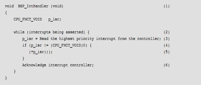
(1) Here assume that the handler for
the interrupt controller is called from the assembly language code that saves
the CPU registers upon entering an ISR (see Chapter 9, ��Interrupt Management�� on page 157).
(2) The handler queries the interrupt
controller to ask it for the address of the ISR that needs to be executed in
response to the interrupt. Some interrupt controllers return an integer value
that corresponds to the source. In this case, simply use this integer value as
an index into a table (RAM or ROM) where those vectors are placed.
(3) The interrupt controller is asked to
provide the highest priority interrupt pending. It is assumed here that the CPU
may receive multiple simultaneous interrupts (or closely spaced interrupts),
and that the interrupt will prioritize the interrupts received. The CPU will
then service each interrupt in priority order instead of on a first-come basis.
However, the scheme used greatly depends on the interrupt controller itself.
(4) Check to ensure that the interrupt
controller did not return a NULL pointer.
(5) Simply call the ISR associated with
the interrupt device.
(6) The interrupt controller generally
needs to be acknowledged so that it knows that the interrupt presented is taken
care of.
��ֲ�����������ִ��룺CPU��OS��BSP��
A
port involves three aspects: CPU, OS and board specific (BSP) code.
��ֲ���� 3 ���ں��ļ��� OS_CPU.H ��
OS_CPU_A.ASM ��OS_CPU_C.C
��C/OS-III
port consists of writing or changing the contents of three kernel specific
files: OS_CPU.H, OS_CPU_A.ASM and OS_CPU_C.C.
��ֲ���� 3 �� CPU �ļ���CPU.H��CPU_A.ASM��CPU_C.C
It
is necessary to write or change the content of three CPU specific files: CPU.H,
CPU_A.ASM and CPU_C.C.
�����Ӧ��Ŀ���İ弶֧�ְ� BSP��
Finally
create or change a Board Support Package (BSP) for the evaluation board or
target board being used.
uC/OS-III
����ֲ������ uC/OS-III ����ֲ
A
��C/OS-III port is similar to a ��C/OS-II port, therefore start from one of the
many ��C/OS-II ports already available (see Appendix C, ��Migrating from ��C/OS-II
to ��C/OS-III�� on page 599).